Editor's note: The following article was adapted from "Thermal Performance Evaluation of Innovative Metal Building Roof Assemblies," which was presented at the International Symposium 2011: Emerging Technologies and Roof System Performance.
Recently, the stringency of energy codes has come into sharp focus with lawmakers and elected officials calling for greater energy efficiency in the codes. Several stakeholders—such as the Department of Energy; The American Institute of Architects; American Society of Heating, Refrigerating and Air-Conditioning Engineers (ASHRAE) Inc.; and other influential groups—have developed plans to move the energy codes toward specific improvement targets.
Currently, ASHRAE 90.1, "Energy Standard for Buildings Except Low-Rise Residential Buildings," provides minimum standards for the energy efficiency of commercial buildings. ASHRAE's plan was to develop a 2010 edition of ASHRAE 90.1 that would provide 30 percent more energy savings compared with the 2004 edition. To meet this challenge, a number of significant changes to the standard needed to take place for design requirements in lighting, HVAC equipment and various building envelope improvements.
History
In 1999, the format and compliance options for the building envelope provisions of ASHRAE 90.1 moved away from a single minimum U-factor (thermal transmittance) for walls and another for roofs (regardless of construction type). This change was made to recognize the variety of constructions commonly found in U.S. building stock. Three categories of roof construction were established at that time: Insulation Entirely Above Deck, Metal Building, and Attic & Other. Likewise, the following common building wall types were established: Mass, Metal Building, Steel Framed, and Wood Framed & Other. The "other" designation is included to ensure roof or wall types not specifically defined still must meet one of the minimum performance requirements.
Various climate zones were established in ASHRAE 90.1 to recognize the variety of weather throughout the U.S. For each defined roof and wall construction, the minimum building envelope U-factor, F-factor and C-factor requirements for each climate zone are determined based on the economic benefit that selecting the requirement will provide.
Determining minimum requirements
Unlike building codes, energy code requirements are not life-safety driven. Because of this, energy codes instead must focus on mandates of efficiency or economic cost justification to determine reasonable requirements given a certain payback period. Currently, ASHRAE 90.1 focuses on both, having adopted a plan to reduce the total energy use of new buildings by 30 percent while attempting to do so cost effectively.
To achieve the 30 percent energy savings goal, the savings must be derived from a blend of cost-effective measures, including improving insulation and fenestration performance; reducing air infiltration through roofs, walls, windows and doors; improving HVAC efficiency; and requiring more efficient lighting systems and controls.
To select appropriate prescriptive insulation performance requirements for roofs and walls, two basic pieces of information must be known for each evaluated assembly: the total insulating performance and total per-square-foot in-place cost of each proposed assembly. The thermal transmittance accounts for the thermal bridges (short circuits) that occur in assemblies because of framing, voids, gaps and fasteners.
Research
At the time ASHRAE 90.1-1999 was developed, there were only a handful of metal building roof details with performance data provided by the North American Insulation Manufacturers Association (NAIMA). NAIMA's data was developed through hot box testing and finite difference modeling. Normative Appendix A of ASHRAE 90.1 contains a library of known U-factors for various construction types, including those for metal building roof and wall systems.
The call for a 30 percent decrease in total building energy use for ASHRAE 90.1 prompted the Metal Building Manufacturers Association (MBMA) to review the known insulation systems in Appendix A. Because the details were developed in 1999 and at that time the insulation requirements in ASHRAE 90.1 were relatively low, Appendix A did not contain a variety of high-performance metal building roof system designs. Also, for metal buildings, the appendix was based on the use of mostly fiberglass insulation and did not contain many of the alternative insulation options that have become available since that time. Space limitations exist because of the construction details of typical metal building roof assemblies; therefore, details that used combinations of fiberglass, rigid board or reflective insulations were considered to be possible solutions that had not yet been studied or verified through hot box testing.
A diverse working group of professionals representing manufacturers and suppliers to the metal building industry was formed by MBMA to help design experiments that might uncover potential areas for improving existing common details and to conceive new, more energy-efficient roof details for metal building systems. The group also set a target performance of U-0.040 Btu/(h•ft2•°F) or better. It should be noted MBMA members do not provide or typically design insulation systems. However, new insulation systems could affect the structural framework and design that must be considered by manufacturers.
The research focused on improving the thermal transmittance of metal building roof systems. The method used to determine the U-factor performance of each of the studied assemblies was ASTM C1363, "Standard Test Method for Thermal Performance of Building Materials and Envelope Assemblies by Means of a Hot Box Apparatus." This method was chosen because ASHRAE recognizes the hot box method as being an appropriate method of determining a metal building roof assembly's U-factor. ASHRAE currently does not allow calculation procedures for determining U-factors for metal building assemblies because of their complexity and the potential for thermal bridging of metal components.
Performance experiments
The Buildings Technology Center at Oak Ridge National Laboratory (ORNL), Oak Ridge, Tenn., was used to conduct steady-state guarded hot box evaluations in its Large Scale Climate Simulator to determine the overall U-factor of MBMA's standing-seam metal roof systems with purlins spaced 4 feet on center. The simulator provides controlled conditions above and below roof test sections so test modules can be evaluated in accordance with ASTM C1363. The test module dimensions were 12 1/2 feet by 12 1/2 feet with an 8- by 8-foot metering area.
Experienced industry personnel completed the design and construction of the four tested assemblies. Tests were conducted with two purlins (effectively 4 feet on center) in the simulator's metered area. It is worth noting typical roof purlin spacing for metal buildings is 5 feet on center, but the simulator's metering area is not compatible with 5 feet on center.
It is possible to evaluate the performance of assemblies with compatible smaller and larger spacings and then develop a curve fit to estimate performance with 5 feet on center. For this research, the decision was made to test the assemblies at 4 feet on center to obtain performance results directly from testing instead of a curve fit. Further, by performing the tests at a smaller spacing, the thermal bridging of these assemblies should be greater than those spaced 5 feet on center and, therefore, conservative.
Details
Two test assemblies (Modules 1 and 2) used R-25 unfaced fiberglass insulation in the cavity between purlins and R-13 unfaced fiberglass insulation over the purlins with about 1 1/4-inch-thick foil-faced polyisocyanurate board insulation attached to the bottom of the purlins.
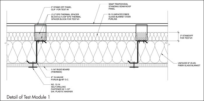
Detail of Test Module 1
Modules 1 and 2 were the same base assembly with only one variation, which was roof clip height. Module 1 used a specially fabricated 3-inch stand-off panel clip with 2 5/8-inch-thick thermal spacer blocks between clips to support the metal roof panel in the flats. Module 2 used a standard 1 3/8-inch stand-off panel clip with 5/8-inch-thick thermal spacer blocks between clips. Great care was taken to prevent disturbing the fiberglass and rigid board insulation during the change from Module 1 to Module 2.
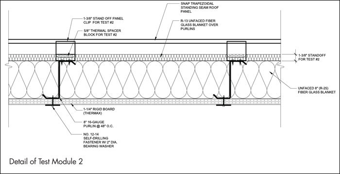
Detail of Test Module 2
The third module was constructed by replacing the R-13 fiberglass top layer and 5/8-inch-thick thermal spacer blocks in Module 2 with 3/8-inch-thick reflective insulation and 1-inch-thick thermal spacer blocks. The nominal R-values for the expanded polystyrene thermal spacer blocks is expected to be approximately R-3.85 per inch and R-6.5 per inch for the rigid board used in Modules 1 through 3.
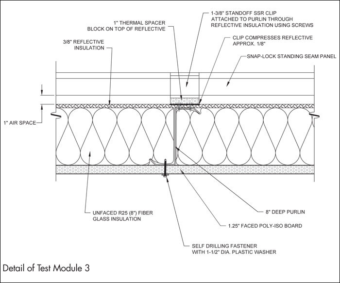
Detail of Test Module 3
Module 4 consisted of two metal panels with the first panel being the metal liner panel installed by screwing it directly to the purlins. Roof stand-off clips (12 inches tall) were used to raise the roof surface above the purlins, creating a 12-inch cavity. R-30 and R-13 unfaced fiberglass were installed on top of the metal liner panel in this cavity. The top panels were installed using zero-clearance roof clips attached to hat channels.
The test module was fully instrumented with thermocouples on the upper and lower surfaces. A grid was positioned above the upper surface to measure the air temperature in the climate chamber with 24 thermocouples. A similar grid was in place permanently in the metering chamber below its top edge with 21 thermocouples. The purpose of this insulation is to lessen the thermal load on the guard chamber. The amounts of insulation around the perimeter and the quality of its installation do not affect the energy flow through an assembly's metered area.
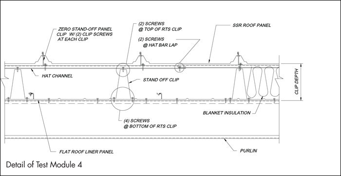
Detail of Test Module 4
The metering chamber was raised and sealed against the bottom of each test module. Masking tape was used to seal the outside top edges of the metering chamber walls. No air pressure differences were imposed between the guard and metering chambers below the test section or between these chambers and the climate chamber above the test section. All heat was assumed to flow into or out of the metering chamber by conduction through the test section and metering chamber walls.
Energy into or out of the metering chamber was measured in accordance with ASTM C1363. The energy flow for the walls and floor was determined as a function of the measured surface temperature imbalance by previous use of a calibration panel—that is, a simple test section with known thermal resistance. Energy flow through the metering chamber walls and floor was the sum over all faces. On each wall and the floor, the average temperature difference measured by nine differential thermocouples was multiplied by the component's area and divided by its R-value.
After the final test temperature conditions were reached (thermal steady-state condition), at least five successive repeated data sets were obtained. These sets were obtained at a time interval equal to the time constant of three hours for a total of 18 hours of data taken every five minutes. Reported values are averages of the readings during these 18 hours of thermal steady-state condition. Reported deviations are two standard deviations of the readings during the same period.
The same calibration panel was used periodically to establish the accuracy and precision of energy balances for the metering chamber. The accuracy generally is about plus or minus 10 percent. The precision or reproducibility generally is about plus or minus 1 percent as a result of excellent control of imposed conditions by the control system. Proportional-integral control is achieved using a Programmable Logic Controller.
Results and discussion
The air temperatures imposed in the climate and metering chambers yielded a mean insulation temperature of 75 F for heat flow upward tests (winter condition). The heat flow upward evaluations were conducted with the climate chamber at 50 F and metering chamber at 100 F. Guard chamber temperatures were kept at the metering chamber condition to minimize the heat flow between the guard and metering chambers.
The ASHRAE R-values measured for Modules 1 and 2 were R-37.2 h•ft2•°F/Btu (U-0.0269 Btu/[h•ft2•°F]) and R-33.0 h•ft2•°F/Btu (U-0.0303 Btu/[h•ft2•°F]), respectively. Lower R-values of Module 2 compared with Module 1 are a result of the compression of the insulationwith shorter clips. Following completion of the heat flow upward test on Module 2, the test was repeated to check the reproducibility of the results. The repeat test result was found to be R-33.3 h•ft2•°F/Btu (U-0.0300 Btu/[h•ft2•°F]), which shows a difference of 0.97 percent as a result of excellent control of imposed conditions.
The ASHRAE R-values measured for Modules 3 and 4 were R-30.6 h•ft2•°F/Btu (U-0.0327 Btu/[h•ft2•°F]) and R-32.1 h•ft2•°F/Btu (U-0.0312 Btu/[h•ft2•°F]), respectively. The procedure's variability also was tested with the removal of Module 4 from the simulator and reinstallation at a later date. The reinstalled Module 4 was re-evaluated at the heat flow upward condition. The ASHRAE R-value for the reinstalled Module 4 was found to be R-30.1 h•ft2•°F/Btu (U-0.0332 Btu/[h•ft2•°F]). This shows a variability of about 6 percent.
Insulation
Three samples of R-13 unfaced fiberglass blanket used over the purlins in Modules 1 and 2 were taken for testing in accordance with ASTM C518, "Standard Test Method for Steady-State Thermal Transmission Properties by Means of the Heat Flow Meter Apparatus."
The samples, which were about 2 feet by 2 feet, were loaded into a heat flow meter apparatus to determine thermal conductivities at a 75 F mean temperature, as well as mean temperatures of 50 F and 100 F at various thicknesses (resulting in thermal conductivities for different densities). The weight of each sample was measured for the 2- by 2-foot area, as well as the core area of the sample (12 1/2 inches by 12 1/2 inches) representing the area between the transducers in the heat flow meter apparatus.
Similarly, three samples of R-25 fiberglass used between the purlins in Modules 1 through 3 were taken from the metering area. The evaluations of R-25 fiberglass samples were started with thicknesses of 7 inches because of the limitation of the heat flow meter apparatus. The R-30 fiberglass was not evaluated because of the 7-inch limitation of the apparatus. The average thermal resistances were within about 10 percent of the nominal R-value ratings.
Three samples of foil-faced rigid board used at the bottom of the purlins in Modules 1 through 3 were taken from the metered area. Samples of about 2 feet by 2 feet were loaded into a heat flow meter apparatus to determine thermal conductivities at mean temperatures of 50 F, 75 F and 100 F. The average thermal resistances of rigid board were within about 6 percent of the nominal R-value ratings.
Findings
Because of variation in the amount, compression or orientation of the insulations used in the four test modules, it may help to express the performance of each module by calculating the ratio of the simulator measurement divided by the sum of the component-rated R-values of insulation for each system. By doing this, the relative efficiency of each system can be compared even when different R-values or types of insulation are used. The rated R-value was used for this comparison because the quality and recovery of fiberglass insulation can vary and the compression of the fiberglass at supports affects the resistance.
The decrease in relative efficiency of these systems results from compression of the insulation (most prominent in Module 2) or thermal bridging of metal components (seen in Module 4). It is expected the simulator-measured R-values for these systems will improve if a more typical 5-feet-on-center purlin spacing is used; therefore, the tested values should be considered conservative.
The original goal set for this work was to develop innovative metal building roof assemblies that would perform to at least U-0.04 Btu/(h•ft2•°F). All four test modules exceeded this goal, so the research conducted to date should be considered a success.
The results of the tests from Modules 1 and 2 show thermal bridging in metal building roof assemblies can be minimized by increasing the space between the metal roof panel and Z-purlin. The amount of allowable space that can be achieved will be limited by the structural capacity of the roof system under gravity loads and wind-uplift loading. Although there is an energy savings benefit from increasing the height of the metal roof clip, this must be weighed against the costs of qualifying taller roof clips for structural loads, as well as the practicality of installing thick thermal spacer blocks.
It can be deduced that the compression of the top layer of fiberglass insulation was a significant source of insulation performance loss. The results from the Module 1 and 2 tests should give the metal building industry incentive to continue exploring the practicality of providing taller roof clips to minimize the compression of any top layer of insulation.
Module 3's reflective insulation performance showed a moderate decrease compared with Module 2 considering an R-13 fiberglass blanket was replaced with the thinner R-2 reflective insulation. It is recommended that reflective insulation be combined with other forms of insulation, such as fiberglass or rigid board, in heating-dominated climates (heat flow up) because reflective insulation alone would not be as effective at preventing heat loss.
We recommend further investigations of reflective insulations to try to understand the sensitivity of the effective R-value of the reflective insulation as a function of the depth of the air space above and below the reflective insulation. In addition, studies should be performed for the various ASHRAE climate zones to see whether potential for condensation exists on the undersides of metal roof panels that would be exposed to convective currents from any air space necessary for the reflective insulation to work.
The performance of Module 4 was comparable to Modules 2 and 3. Even though this module minimizes the compression of the top insulation layer, the thermal bridging was more significant than in the other tested modules. This module's construction was more labor-intensive, but it has advantages for retrofit use.
Two measurements were recorded for Module 4 because of necessary equipment recalibration resulting from maintenance of the simulator at ORNL. This provided an opportunity to test the variability of the measurement for this assembly, which is more complex than a typical calibration panel because of the need to insulate around any gaps between the test assembly and guard area.
Although no change was made to the assembly, there was a measured difference in performance of about 6 percent in R-value. This difference is the simulator's capability to reproduce R-values, as well as the variability in the test setup and procedure. It is interesting to note that hot box measurements have an inherent amount of uncertainty, and steps should be taken to ensure reported values have a reasonable degree of conservatism built in or multiple measurements are used to average a given assembly's performance.
Future work
Four additional assemblies are in the design phase, and testing is planned to take place in early 2012. One future area of research may be to find ways to reduce the thermal bridging for the assemblies already tested.
This research was intended to examine the possibilities of improving the thermal performance of metal building roof assemblies, and the work is ongoing. This work should be considered research and development, and all aspects of these systems have not yet been evaluated. Additional information related to durability, constructability, structural performance, economics and other factors related to these assemblies must be examined before they are used.
Because each metal building manufacturer has structural test data specific to its roof systems, especially with regard to the clearance between the metal roof panel and the top of the roof purlin, it is imperative installation details are approved by the manufacturer before their use.
Daniel J. Walker, P.E., is a senior staff engineer for MBMA; Abdi Zaltash, Ph.D., is a member of the senior research staff for the Building Envelopes Research Group in the Energy and Transportation Science Division at ORNL; and Jerry Atchley is an engineering technologist at ORNL's Building Technology Center.


COMMENTS
Be the first to comment. Please log in to leave a comment.