 Photo courtesy of the Roofing Industry Committee on Weather Issues
 Photo courtesy of the Roofing Industry Committee on Weather Issues
. A worker makes a test cut to the roof system (top right). Water droplets are found beneath the membrane (bottom right).") Photo courtesy of the National Research Council of Canada
Photo courtesy of the National Research Council of Canada Photo courtesy of the National Research Council of Canada


Field observations have identified that air intrusion in mechanically attached roof systems can affect roof system performance. However, the questions of how much air movement occurs and which components provide the required resistance to air movement have never been addressed.
To measure air intrusion in mechanically attached roof systems, an experimental study has begun at the National Research Council (NRC) of Canada as part of its Special Interest Group for Dynamic Evaluation of Roofing Systems (SIGDERS) research.
Defining the terms
Air movement consists of either air intrusion or air leakage.
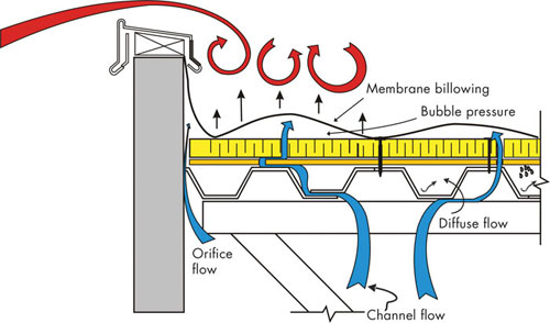
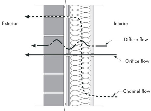
Figure 1: The illustrations demonstrate the concepts of air intrusion in a mechanically attached roof system and air leakage in a brick cladding wall.
Air intrusion occurs when conditioned indoor air enters a building envelope assembly, such as a roof, but cannot leave the assembly to the exterior environment. Air leakage occurs when air enters or leaves one environmental condition to another environmental condition through a building envelope assembly, such as a wall or window.
Figure 1 differentiates the concepts of air leakage and air intrusion through an example of a brick cladding wall and a mechanically attached roof membrane assembly. In membrane roof systems, the waterproofing membrane is impermeable to air. If constructed properly, it can perform as an air barrier, impeding any air movement from the exterior environment to the interior and vice versa. Therefore, in a roof assembly, the membrane may be designated the air barrier and can control air leakage.
In mechanically attached roof systems, because of the flexible and elastic nature of membranes and their attachment mechanisms, wind and mechanical pressurization from the interior can cause a membrane to balloon or flutter. This draws conditioned indoor air into the assembly as shown in Figure 1. The pressure equalization depends on the air intrusion resistance of the components below the membrane (insulation, deck and any other installed roof system components).
The effects of air intrusion
Being able to control air intrusion is critical to roof system design because air intrusion can have several effects on roof system performance, specifically on wind uplift, condensation and energy.
A mechanically attached roof system's wind-uplift resistance depends on the membrane's response to wind dynamics. Fluttering during wind action creates a region of low pressure below the membrane. To equalize the pressure, indoor air intrudes into the system. If the roof components below the membrane do not sufficiently resist air intrusion and the rate of air intrusion is rapid, the combination of the positive and negative uplift forces on the membrane, which resists the entire uplift load, could lead to the failure of the membrane and system. This is illustrated in Photos 1 and 2.
Apart from diffusion, which causes water vapor transportation into roof systems, the other significant mechanism of moisture entry into a roof system from a building's interior is air intrusion. The dew point is the temperature at which water vapor begins to condense. Dew point temperature can occur below the membrane and within the insulation. When warm, humid air—which has a high water vapor content—is drawn into a roof assembly and contacts surface materials at the dew point temperature, it condenses as shown in Photos 3, 4 and 5. Condensation can lead to wet insulation, which will reduce the insulation's thermal performance and affect the roof assembly's energy performance.
Apart from a roof assembly's opaque portion, a roof structure also can provide a path for air intrusion through expansion joints; unsealed penetrations of the structure through walls; continuous flutes and gaps in steel decks; and structural support for rooftop equipment (air intake and exhaust vents, plumbing vent stacks, roof drains, skylights and electrical conduits). If the plane of airtightness is not provided within a roof assembly at the appropriate location, these flow paths tend to multiply the amount of airflow, negatively affecting the roof assembly's energy performance.
Quantifying air intrusion
Cautions regarding air intrusion are not new. There are existing technical notes, manuals and papers that have identified how air intrusion affects roof assembly performance. However, no information is available regarding the amount of air intrusion that can occur in mechanically attached roof systems or their sensitivity to air movement.
The role of vapor retarders and air barriers in mitigating air movement in building envelopes first was introduced into the National Building Code of Canada in 1965, and the 1985 revisions provided minimum air leakage requirements for air barrier materials and systems. In the U.S., Wisconsin has used air barriers in state-owned projects since 1985, and in 2001, Massachusetts became the first state to require air barriers in its energy code. In 2007, the American Society of Heating, Refrigerating and Air Conditioning Engineers (ASHRAE) Inc. approved a revised version of ASHRAE 90.1, "Energy Standard for Buildings Except Low-Rise Residential Buildings," that includes requirements for air barriers.
Although these regulatory requirements and the available test standards clearly identify that an airtight envelope can help buildings function more appropriately, the primary focus of these requirements has been on wall assemblies. But as we discussed, in roof assemblies, air movement often is misunderstood as is the location of the primary plane of airtightness and its construction.
To measure the air intrusion in mechanically attached roof systems, a new test laboratory has been developed at NRC, and new test protocol has been conceptualized. The test protocol has been submitted as a work item to ASTM International for standard development. The test method's scope is to compare the air intrusion in low-slope membrane roof assemblies under specified negative air pressures with the same roof assemblies free from penetrations such as those associated with mechanical devices, roof junctions and terminations.
How do you measure it?
The test consists of installing a membrane assembly specimen between two chambers, specifically an airtight bottom chamber into which air flows and a top chamber that exhausts air at the rate required to maintain the specified negative pressure across the membrane assembly. The resultant air intrusion into the membrane assembly is measured from the airflow measurement system installed on the bottom chamber.
The test apparatus is shown in Photos 6-15. It is composed of a movable two-section top chamber and closed bottom chamber; each has a dimension of 20 feet by 8 feet by 3 feet. The membrane assembly is installed horizontally at the top of the bottom chamber, which supports a height-adjustable lever that can accommodate membranes with different thicknesses. Test pressures (negative or suction pressures) are applied as per ASTM WK23684, "Standard Test Method for Quantification of Air Intrusion in Low-sloped Mechanically Attached Membrane Roof Assemblies," on the test specimen through a controllable blower connected to the top chamber.
To measure the air intrusion into the roofing specimen, the bottom chamber is installed with an airflow measurement system. The differential pressure across the test specimen is measured by installing two pressure measuring devices, one on top of the membrane and the other above the insulation.
Developing the data
As part of SIGDERS research, control data were developed by quantifying the air intrusion rate of mechanically attached roof systems with and without air retarders. Three types of roof systems—polymer-modified bitumen, thermoplastic and thermoset—were tested. Apart from the membrane type and installation, all other roof components, such as the steel deck, insulation type and layout, and air retarder type and layout were similar for all the tested assemblies.
Photos 6-15 show the layout and assembly installation of the tested assemblies. The components used for the tested assemblies were:
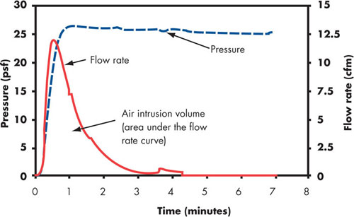
Figure 2: Typical time history plot of the air intrusion data measured during testing
Following the ASTM WK23684 test protocol, each specimen was subjected to negative pressures ranging from 5 pounds per square foot (psf) to 25 psf in increments of 5 psf. At the applied negative pressures, the membrane and insulation pressures and the flow rates were measured. From the measured flow rate, the volume of air intrusion into the roof specimens was computed as shown in Figure 2. As per the proposed ASTM WK23684, at the reference pressure of 25 psf, the air intrusion volume was reported.
What influences air intrusion?
Figure 2 shows the tested assemblies' air intrusion performance. A significant parameter that influences air intrusion in a mechanically attached roof system is sheet width. The study evaluated three sheet widths: 3, 6 and 10 feet. The 3-foot-wide sheet represents the minimum sheet width, and using this as the benchmark, the air intrusion performance of the 6- and 10-foot-wide sheets are compared.
As shown in Figure 3, the system with the 3-foot-wide sheet had an air intrusion volume of 27 L/m2. When the sheet width was increased to 6 feet, the volume of air intrusion into the system also doubled, increasing to 54 L/m2. When the sheet width further increased to 10 feet, as in the case of the thermoplastic and thermoset systems, the volume of air intrusion into both systems also tripled to 88 L/m2.
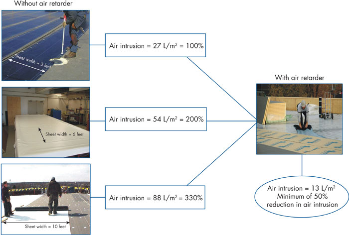
Figure 3: Air intrusion volume of the tested mechanically attached roof assemblies
The data indicates membrane material type is not a major contributor compared with the bubble volume. In other words, with all similar roof assembly components except the membrane type and membrane width, the data indicate the increase in the sheet width increases the bubble volume during wind action, and, therefore, the volume of air intruding into the roof system increases.
When air retarders were installed on the assemblies' decks, the air intrusion rate reduced 50 percent in the 3-foot-wide polymer-modified bitumen systems, about 75 percent in the 6-foot-wide thermoplastic systems and about 85 percent in the 10-foot-wide thermoset systems compared with systems without air retarders.
The air intrusion volume of the three assemblies with air retarders is similar with an average air intrusion volume of 13 L/m2, indicating that irrespective of the assembly type and configuration, the presence of an air retarder at deck level, if constructed properly, minimizes air intrusion. Even though the results represent the air intrusion performance of only one air retarder type, further research with different types of air retarders and to quantify other influencing parameters will be conducted as part of ongoing research (see "Ongoing research," page 30).
How much intrusion is too much?
Research conducted at NRC for the SIGDERS consortium has demonstrated the wind-uplift resistance of mechanically attached roof systems can be increased as much as 50 percent by including an air retarder regardless of the air retarder type. This finding can be justified from the measured air intrusion data shown in Figure 3.
The air intrusion reduction is what differentiates the wind-uplift performance of assemblies with and without air retarders. As discussed previously, in the case of assemblies without air retarders, the pressure difference above and below the deck equalizes and the roof membrane resists the uplift force. With air retarders, the pressure difference acts on all the component layers beneath the membrane and the uplift force is shared among the components, which theoretically allows the roof system to sustain higher wind-uplift pressures.
Although an air retarder contributes to improved wind-uplift performance, questions arise whether it is necessary that an air retarder be completely air-impermeable to achieve the required wind-uplift-resistance rating. It should be understood that some quantity of air intrusion may negatively affect roof system performance in terms of wind uplift, condensation and energy.
Good design practice tells us to prevent the movement of moisture-laden air into roof assemblies, which can be achieved by installing a continuous air retarder at the deck level. However, complete airtightness can lead to trapped vapor between two impermeable air retarders, which begs the question: What is the maximum allowable amount of air intrusion that can be tolerated in a mechanically attached roof system before moisture entry and the attending risk of condensation will adversely affect its performance?
To answer this question, a research project is in progress in collaboration with NRCA; the Canadian Roofing Contractors' Association; Carlisle SynTec Canada, Oakville, Ontario; Dow Roofing Systems, Holyoke, Mass.; Firestone Building Products Co., Mississauga, Ontario; and Sika Sarnafil, a business unit of Sika Canada, Mississauga. The study aims to establish air intrusion limits in mechanically attached roof systems for building code recommendations.
Next steps
Through a new ASTM International test protocol, research at NRC has defined the volume of air intrusion occurring in mechanically attached roof systems. Data indicate that systems with larger sheet widths have higher volumes of air intrusion compared with systems with narrower sheet widths, and the presence of air retarders could reduce a minimum of 50 percent of air intrusion into the systems. To determine the limits of air intrusion for building code recommendations and quantify air intrusion's effect on condensation control and energy performance, further research is being conducted by roofing organizations.
Bas Baskaran, Ph.D., P. Eng., is a group leader and Suda Molleti, Ph.D., is a research officer for the roofing subprogram at the National Research Council of Canada's Institute for Research in Construction.
The Special Interest Group for Dynamic Evaluation of Roofing Systems (SIGDERS) was formed from the following group of partners interested in roof system design:
Atlas Roofing Corp., Atlanta
Canadian General-Tower Ltd., Cambridge, Ontario
Canadian Roofing Contractors' Association
Carlisle SynTec Inc., Carlisle, Pa.
Dow Roofing Systems, Holyoke, Mass.
Duro-Last® Roofing Inc., Saginaw, Mich.
Firestone Building Products Co. LLC, Indianapolis
GAF Materials Corp., Wayne, N.J.
IKO Industries Ltd., Brampton, Ontario
Johns Manville, Denver
NRCA
OMG Roofing Products, Agawam, Mass.
Public Works and Government Services Canada
RCI Inc.
Sika Sarnafil, Canton, Mass.
Soprema Canada Inc., Drummondville, Quebec
Tremco Inc., Toronto, Ontario
TRUFAST Corp., Bryan, Ohio


COMMENTS
Be the first to comment. Please log in to leave a comment.