Contractor-fabricated architectural metal panel roof systems have been used successfully in the United States for years. However, there recently has been increased scrutiny about some of these roof assemblies' wind uplift-resistance capabilities.
Building code requirements mandate minimum uplift resistances for roof assemblies, and model building codes list approved test methods that determine uplift resistances for roof assemblies that cannot have uplift resistances determined analytically. Underwriters Laboratories (UL) Inc. test method UL 580, "Tests for Wind Uplift Resistance of Roof Assemblies," currently is the most common method referenced in building codes as an approved test method to determine uplift resistance of roof assemblies.
For most roofing products used in the United States, roofing contractors rely on product manufacturers to perform testing and provide the necessary documentation for building code compliance. However, because there are no product manufacturers for contractor-fabricated architectural metal panel roof systems, the responsibility for providing code compliance information typically resides with the contractor who fabricates and installs the metal panels. Steel and aluminum have analytical design methodologies that are industry-accepted; there is no industry-accepted analytical design methodology for copper. Therefore, the uplift resistances of copper panel roof systems must be determined through physical testing.
Because of this, in 1997, NRCA embarked on a testing program for contractor-fabricated copper panel roof systems. All metal panels in this study are flat-pan with double-lock standing seams. NRCA retained and analyses were performed by ENCON® Consultants Inc., Tulsa, Okla., at the Hurricane Testing Laboratory in West Palm Beach, Fla. As part of our study, theoretical analyses of contractor-fabricated aluminum, Galvalume,™ galvanized steel, terne-coated stainless steel and terne-coated carbon steel roof panels were performed to determine uplift resistances according to standard design practice.
Explanation of study
The uplift-load capacities of standing-seam roof systems depend on a number of factors, such as panel material, panel configuration, number of spans and span length (clip spacing), sidelap seam configuration, clip strength and attachment, and other related factors. A roof system's uplift capacity is limited by its weakest link, or initial failure mode. The primary objective of the analytical study and small-scale bench test studies was to establish a roof system's weakest link. Then, the weakest link's allowable load capacity was assessed and used to determine a roof system's resistance to uplift load.
Small-scale tests
One way to establish a roof system's weakest link is by conducting small-scale tests of a clip assembled in various panel sidelaps. The results of small-scale clip tests with a clip seamed into various panel sidelaps can be used to evaluate failures.
Small-scale tests were conducted to establish the uplift resistance of a 24-gauge-thick stainless-steel clip when the clip was seamed into different panel systems. (See Figure 1 for the panel system types tested.) During testing of the different systems, failure included yielding of the panel, crushing of the male rib and pull-over failure of the panel clip base.
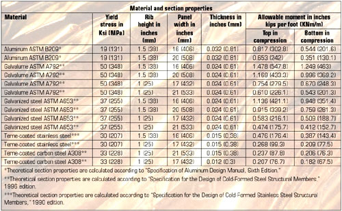
Figure 1: A summary of allowable moments for various metal roof systems
The uplift resistance of the clip-fastener assembly when attached to 15/32-inch- (11.9-mm-) and 23/32-inch- (18.3-mm-) thick plywood sheathing was tested. Failure modes observed in these tests included fastener pull-out failure and clip base pull-over failure.
The small-scale clip tests with the clip inserted in the various panel sidelaps suggest that with at least some of the materials under consideration, the panel clip assembly will be the weakest link. For example, some failures are the result of male sidelap crushing under the clip, failure of the clip by pulling the clip base over the head of the screw and the screws pulling out from the substrate material.
Theoretical calculations
Determining a roof system's weakest link also included determining the beam strength of a panel seam between clips for a three-span condition. Section properties for each panel were calculated according to the appropriate design manual for a given material type and yield stress. The allowable moment then was calculated for two conditions. A summary of allowable moments for various metal panel systems is shown in Figure 1.
Full-scale testing of panels with double-locked seams has shown that a clip typically is well-restrained in such seams and crushing of a panel's male rib is the most common failure mode. The theoretical calculations establish that the weakest link in the possible failure modes under actual wind load will not be panel sidelap beam failure between clips.
Yield-strength tests of a panel at its point of maximum moment were conducted to determine the failure of a panel sidelap as a beam between clips. From this, we concluded the panel sidelap beam that spans between clips is not the weakest link for clip spacing less than or equal to 2 1/2 feet (762 mm).
Allowable load calculation
The allowable uplift load that can be carried by each panel system was calculated for clips installed in 15/32-inch- (11.9-mm-) and 23/32-inch- (18.3-mm-) thick plywood. The clip spacing or panel span varied from 1 foot (305 mm) to 2 1/2 feet (762 mm). The allowable uplift loads are based on the following criteria and safety factors:
Discussion
The small-scale bench-type tests of clips do not completely simulate actual field conditions under full-scale wind-uplift load conditions. There is a possibility that under actual load conditions, with at least some materials, there may be interaction between the various elements that will cause a premature failure or failure at a lower load than we identify in this article. And there is a possibility that under actual load conditions, the failure load may be higher.
Another factor that may cause loads to vary from the loads actually obtained under simulated wind load conditions, as established in the allowable load tables, relates to the potential inclusion of an airtight barrier on the substrate. The loads established in the allowable load tables do not take into account that in the field, the panels will be installed over plywood and the plywood substrate and/or other component may form an airtight barrier. If this occurs, at least some uplift load will be resisted by the plywood substrate. The load on a metal roof system will be reflected onto the plywood; therefore, the roof system's uplift capacity will be greater than the established allowable load on the panel and its attachment. From an engineering perspective, this would benefit overall uplift-resistance capability, making the calculated loads conservative.
Explanation of UL 580
UL 580, "Tests for Uplift Resistance of Roof Assemblies," subjects a 10- by 10-foot (3.05- by 3.05-m) roof assembly sample to various static and oscillating pressures; these are intended to represent the uplift forces imposed on a roof assembly exposed to high winds.
The test is divided into four levels with increasing pressures that correlate to Class 15, Class 30, Class 60 and Class 90. Roof assemblies passing this test are assigned one of the classifications.
Each classification is divided into five phases: static negative pressure for five minutes; static negative and positive pressures for five minutes; oscillating negative and static positive pressures for 60 minutes; static negative pressure for five minutes; and static negative and positive pressures for five minutes. See Figure 2 for test pressures.
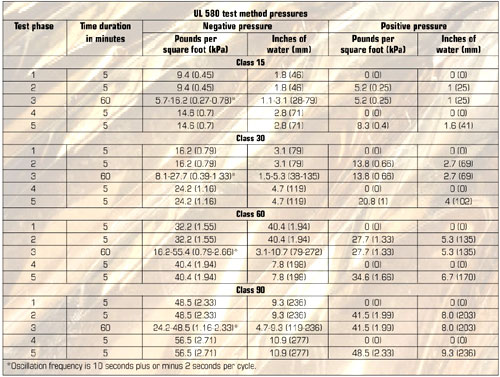
Figure 2: Test pressures to which metal roof assemblies are exposed
The maximum total pressure applied to a roof assembly test specimen for Class 15 is 22.9 pounds per square foot (psf) (1.1 kPa); for Class 30, it is 45 psf (2.16 kPa); for Class 60, it is 75 psf (3.6 kPa); and for Class 90, it is 105 psf (5.04 kPa).
A roof assembly receiving a Class 90 rating has endured four hours of static and oscillating pressures without failure. To receive a Class 90 rating, it is not required the Class 15 level be used. However, Class 30 and 60 levels are required. The UL 580 testing protocol performed for NRCA did not include the Class 15 level.
Explanation of UL 1897
UL 1897, "Uplift Tests for Roof Covering Systems," subjects a 10- by 10-foot (3.05- by 3.05-m) roof assembly sample to various static pressures. These pressures are intended to represent the uplift forces imposed on a roof assembly exposed to high winds.
The test consists of multiple phases of 15-psf (0.72-kPa) increments beginning at 15 psf (0.72 kPa). Roof assemblies passing this test are assigned classifications of Class 15, Class 30, Class 45, Class 60, Class 75, Class 90, Class 105, etc.
Each phase consists of static negative pressure for one minute. If the roof assembly sample passes, the pressure is increased to the next increment for one minute. The roof assembly rating is the maximum static negative pressure sustained for one minute without failure.
Explanation of test results
NRCA's intent was to achieve a UL 90 classification with the least conservative copper panel roof assembly that commonly is installed and would pass. This would facilitate a UL 90 classification of more conservative panel assemblies based on future engineering analyses. Achieving a UL 90 classification with the most liberal panel assembly provides the opportunity for the largest number of possible copper panel roof assemblies to be evaluated via an engineering analysis and qualify to have a UL 90 classification.
NRCA believed a double-lock seam was the most appropriate seam to test. Such a seam generally is considered to be the most weatherproof and strongest seam type available. Also, NRCA initially presumed a taller double-lock seam (1 1/2 inches versus 1 inch [38.1 mm versus 25.4 mm]) would provide greater uplift resistance.
NRCA decided to initially test the least conservative clips and clip spacing (wide). We chose to begin with a two-piece, 28-gauge-thick stainless-steel clip at 24 inches (610 mm) on center.
Testing—part one
The initial UL 580 test was performed in May 2000 on 21-inch- (533-mm-) wide, 16-ounce-per-square-foot (0.0216-inch- [0.56-mm-] thick) copper panels meeting ASTM B370, "Standard Specification for Copper Sheet and Strip for Building Construction," with 1-inch- (25-mm-) tall double-lock standing seams and 28-gauge-thick, two-piece stainless-steel expansion clips at 24 inches (610 mm) on center. The roof assembly failed the test during the 60-minute phase of the UL 60 classification level as a result of buckling of panel seams and panels. Therefore, the copper panel assembly achieved a UL 30 rating. Because the test results did not satisfy NRCA's objective, NRCA is not pursuing a UL listing for this tested configuration.
Based on the analysis of the failed assembly, the clips did not appear to be part of the failure mode; the clips did not appear significantly deformed during the test. However, because of the buckled seams, we believed the clip spacing was too wide, allowing for substantial seam deflection. The seam deflection led to panel buckling, which constituted roof assembly failure.
Because the failure mode was initiated by buckled seams, we predicted a taller seam would provide more uplift resistance. This prediction follows engineering logic that deeper beams (taller seams) provide greater resistance to deflection under similar loads. The clip spacing also was reduced to provide another more conservative parameter to the assembly.
Testing—part two
The second UL 580 test was performed in April 2001 on 20-inch- (508-mm-) wide, 16-ounce-per-square-foot (0.0216-inch- [0.56-mm-] thick) copper panels meeting ASTM B370 with 1 1/2-inch- (38-mm-) tall, double-lock standing seams with 28-gauge-thick, one-piece stainless-steel clips at 18 inches (457 mm) on center. The roof assembly failed the test during the five-minute phase of the UL 60 classification level because of buckling of panel seams. Therefore, the copper panel assembly achieved a UL 30 rating. Because the test results did not satisfy NRCA's objective, NRCA is not pursuing a UL listing for this tested configuration either.
Based on the analysis of the failed assembly and comparison with the failure mode of the initial test, it was apparent the seam height caused panel seams to buckle. The panel assembly did not perform as well as the initial assembly tested. The panel in this test had narrower panel ribs and closer clip spacing than the panel used in the initial test. Therefore, we concluded taller panel seams caused the failure.
And because neither panel assembly passed the UL 60 classification, another parameter of the test assembly needed to be more conservative. We decided to test narrower panels, use 1-inch- (25-mm-) tall seams and retain the 18-inch (457-mm) on-center clip spacing.
Testing—part three
The third UL 580 test was performed in April 2001 on 17-inch- (432-mm-) wide, 16-ounce-per-square-foot (0.0216-inch- [0.56-mm-] thick) copper panels meeting ASTM B370 with 1-inch- (25-mm-) tall, double-lock standing seams with 28-gauge-thick, one-piece stainless-steel clips at 18 inches (457 mm) on center. The roof assembly passed the UL 90 classification cycle.
"Passing" implies the roof assembly is functional and weatherproof, not that the roof assembly would remain aesthetically acceptable to a building owner. With more than 2 inches (51 mm) of permanent deflection at the center of the middle panels, it is unlikely any owner would allow such a roof system to remain in place. However, the roof assembly will keep water out of a building and provide reliable weatherproofing.
Comparing test methods
NRCA decided to test its UL 90-rated metal panel roof assembly by an alternative test method, the UL 1897 test method, to see whether a test method influences ultimate failure load (the resultant classification). The test methods' durations differ significantly. To achieve a UL 90 classification from the UL 580 test method, a roof assembly must endure four hours of testing. Comparatively, to achieve a UL 90 classification from the UL 1897 test, a roof assembly must endure about 12 minutes of testing. The 12 minutes represent six one-minute phases and the approximate time to increase pressure before beginning each phase.
The UL 1897 test was performed in November 2001 on 17-inch- (432-mm-) wide, 16-ounce-per-square-foot (0.0216-inch- [0.56-mm-] thick) copper panels meeting ASTM B370, with 1-inch- (25-mm-) tall, double-lock standing seams with 28-gauge-thick, one-piece stainless-steel clips at 18 inches (457 mm) on center. This is the same assembly that achieved a UL 90 classification by the UL 580 test method. It also achieved a UL 165 classification from the UL 1897 test method.
It is apparent the test methods' durations significantly affected the results. Without further testing, it is unknown whether the UL 1897 test method consistently will result in nearly double the classification of the UL 580 test method.
Conclusions
The allowable uplift loads for metal roof system panels are provided in Figure 3. This includes the use of 24-gauge-thick stainless-steel clips installed in 15/32-inch- (11.9-mm-) thick plywood for the various spans.
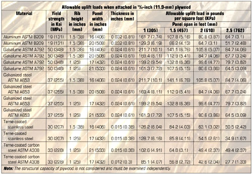
Figure 3: Allowable uplift loads of tested panels
The conclusions drawn from the testing of the copper panel roof systems are based on visual observations made during the testing. It is apparent additional work could be done to further verify these conclusions. However, the information gained during this testing is invaluable and should be considered if further tests are performed.
We came to several conclusions as a result of the testing. For example, clip spacing is more critical to uplift resistance than panel width; buckling of panel seams initiated panel buckling; and panel buckling was the failure mode in this study.
In addition, seam height affects a panel assembly's uplift resistance. Shorter seams provide greater resistance to buckling—1 inch versus 1 1/2 inches (25 mm versus 38 mm)—in this study. Taller seams begin to spread apart when the flat portions of panels begin to deflect upward during loading conditions. The pan's deflection pulls the bottom portion of the seams away from a vertical position. After the panels deflect significantly, seams' individual sides are pulled apart, resulting in a triangular-shaped seam. This seam distortion changes the physical properties of the double-lock seam. We observed a seam's strength is reduced greatly in this position.
Another conclusion is test parameters affect the resultant uplift-resistance classification. Specifically, test duration significantly affects test results. Identical roof assembly samples were tested under two vastly different test protocols, and the test method with the greatest duration resulted in the lowest uplift-resistance classification.
It is unknown from these tests whether oscillation affects test results more, less or indifferently than duration. We believe oscillation within the 60-minute phase fatigues copper panel clips and seams to some degree. Further study is warranted to determine whether removing the oscillation portion within the 60-minute phase of each level would affect test results.
Editor's note: This article was adapted from a paper that was published in the Proceedings of the 12th International Roofing and Waterproofing Conference on CD-ROM. To purchase the CD-ROM, contact NRCA InfoExpress at (866) ASK-NRCA (275-6722) or access shop.nrca.net.
James R. Kirby is an NRCA senior director of technical services. Bala Sockalingam is a structural engineer with ENCON® Consultants Inc.,Tulsa, Okla.
NRCA's UL listing
NRCA's Underwriters Laboratories (UL) Inc. listing, No. 575, is shown in UL's Roofing Materials & Systems Directory. UL Construction No. 575 provides an Uplift Class 90. NRCA's listing incorporates a copper panel roof system with 17-inch- (432-mm-) wide, 16-ounce-per-square-foot (0.0216-inch- [0.56-mm-] thick) copper panels meeting ASTM B370, "Standard Specification for Copper Sheet and Strip for Building Construction," with 1-inch- (25-mm-) tall, double-lock standing seams with 28-gauge-thick, one-piece stainless-steel clips at 18 inches (457 mm) on center.
This system is required to be installed over any UL-classified base sheet or ply sheet over a minimum 19/32-inch- (15.1-mm-) thick, Grade C-D plywood. Additional requirements are described in the listing.


COMMENTS
Be the first to comment. Please log in to leave a comment.