Editor’s note: Publication of this article should not be construed as NRCA’s agreement with the representations made herein nor an endorsement of ANSI/MCA FTS-1-2019.
The Roofing Industry Committee on Weather Issues Inc. has investigated hundreds of metal panel roof system failures resulting from high-wind events, including Hurricanes Charley, Ivan, Katrina, Ike and Irma. In every RICOWI report, metal flashing failures are cited as a cause of metal panel roof system failures.
A new standard, ANSI/MCA FTS-1-2019, “Test Method for Wind Load Resistance of Flashings Used with Metal Roof Systems,” has been developed by the Metal Construction Association to provide a method for testing metal roof flashings with the goal of improving the wind resistance of metal roof systems. When flashings fail, metal roof panels are exposed at the edges and ridges, and the roof system can peel. When a flashing system has been tested to resist design wind loads, it is less likely to fail, and the roof panels are more likely to stay secure.
Developing a new standard
For low-slope roof systems, flashings are installed at roof perimeters, and for steep-slope roof systems, flashings are installed at the eaves, gables, hips and ridges. These locations are where the highest wind-uplift pressures occur, as calculated using ASCE-7, “Minimum Design Loads and Associated Criteria for Buildings and Other Structures,” so it is critical flashings are designed, manufactured and installed to resist higher wind pressures.
MCA recognizes a key to improving metal roof system performance is to improve the wind resistance of flashings used with these systems. In 2015, MCA formed a steering committee to develop a standard that would prescribe methodology for testing metal roof flashings. The committee members used their extensive industry and field experience and the ANSI/SPRI/FM 4435/ES-1 standard as a template to write the initial draft of a standard for testing metal roof flashings.
After completing the initial draft, the committee sought to judge the standard’s effectiveness. In 2016, it contracted three independent test labs to test five metal roof flashing systems. The committee requested feedback from the labs about the standard and whether the test results were consistent and repeatable among labs.
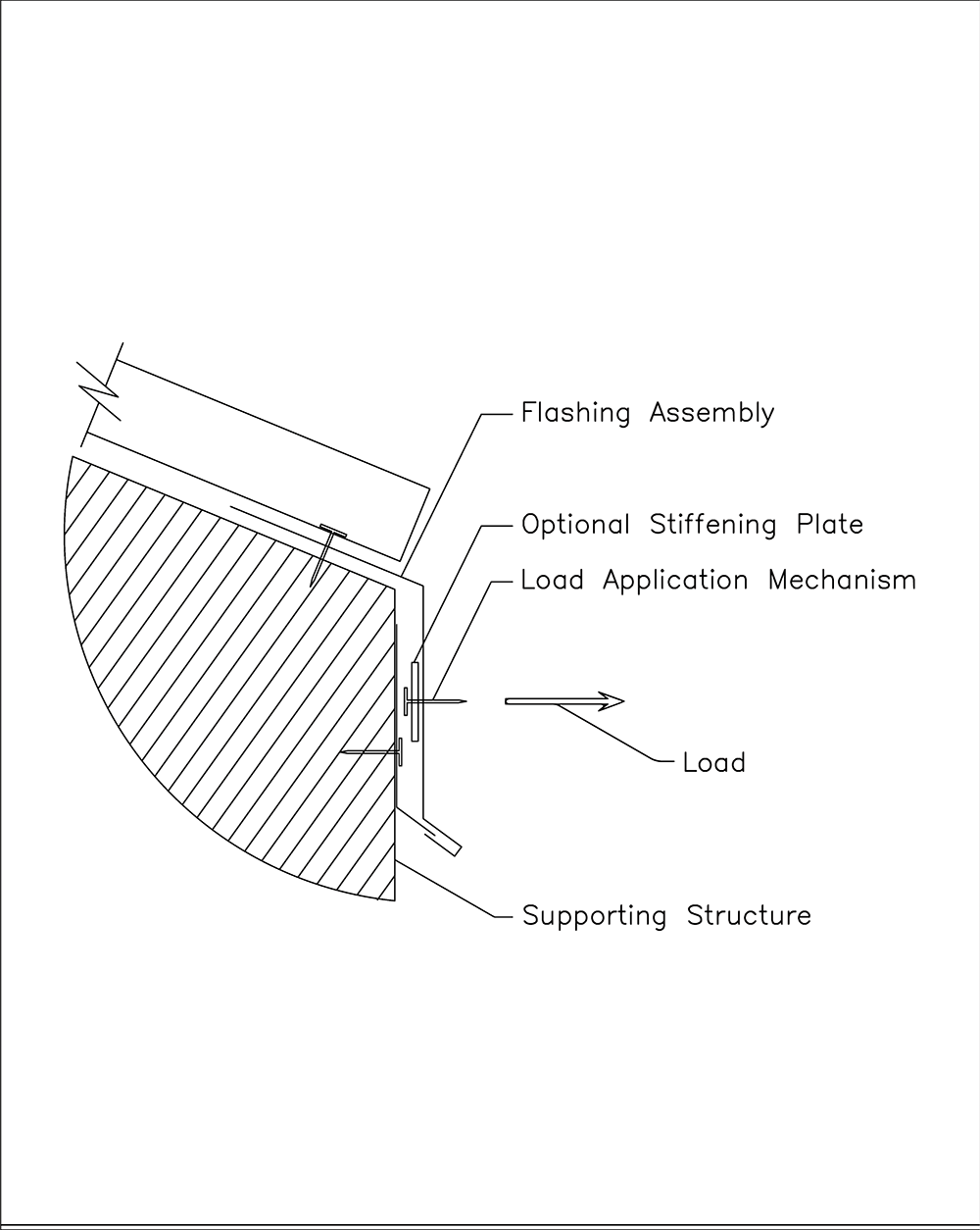 Figure 1: Single-load test apparatus
This testing proved to be valuable for learning how the proposed test methods could be improved, as well as how the language in the standard could be made clearer and more precise. Based on feedback from the test labs and input from others in the roofing industry outside MCA, including SPRI and the Metal Building Manufacturers Association, the MCA committee revised the standard to create a draft that was easier to understand and easier to use.
By late 2017, the MCA committee had a draft document that was ready for development as a consensus-based standard, and it selected SPRI to be the standards developing organization. SPRI formed a task force that worked closely with MCA’s committee to canvass the proposed standard according to SPRI’s ANSI protocol.
Individuals representing many companies and organizations in the roofing industry reviewed the draft standard, voted on it and provided comments to SPRI and MCA. Based on valuable comments received when the proposed standard first was balloted, it was revised and reballoted. Comments received from the recirculation ballot led to additional changes to the standard; however, the changes were deemed to be editorial so there was no need for additional balloting.
The final draft was approved by ANSI June 25, and now is designated ANSI/MCA FTS-1-2019 (FTS stands for flashing test standard).
What’s in the standard?
ANSI/MCA FTS-1 provides only a methodology for testing the wind-load resistance of flashings used with metal roof systems and does not provide information about the calculation of wind loads or the design of flashing systems. The standard consists of four key sections: Test Apparatus, Test Specimen, Loading Procedure and Test Report plus a commentary section explaining the reasoning used when developing the sections.
Test Apparatus
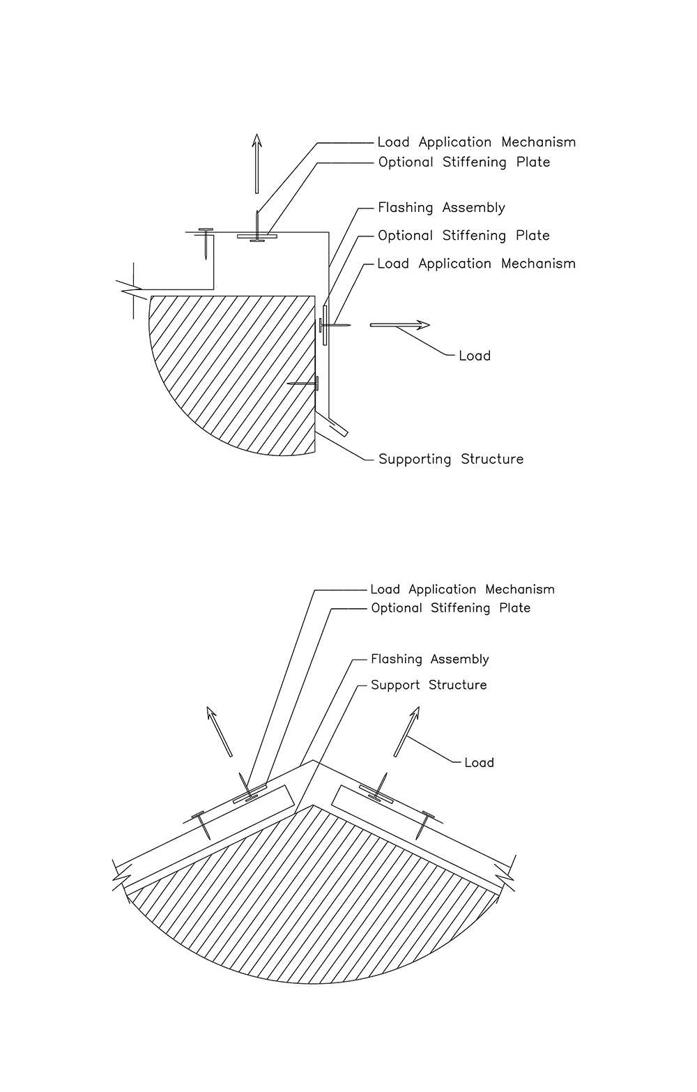 Figure 2 (Top): Two-load test apparatus; Figure 3 (Bottom): Two-load test apparatus
The test requires static loads be applied in either one or two direction(s) at the same time depending on the configuration of the flashing being tested. Therefore, the test apparatus must be capable of applying loads in two directions (typically at 90 degrees to each other) at the same time. The test apparatus must be capable of applying a uniform load down the center of the flashing face at attachment points no greater than 12 inches on center. However, an optional stiffening plate no wider than 2 inches and no thicker than 1/8 of an inch is permitted on the back side of the flashing at the line of the attachment points.
Most test apparatuses used for conducting the tests required by ANSI/SPRI ES-1 would be capable of conducting the test methods of ANSI/MCA FTS-1. Figure 1 shows application of a single load, and Figures 2 and 3 show application of two loads at the same time.
Test Specimen
The flashing test specimen is to be full-size and consist of all parts relevant to the assembly when installed in the field. The specimen must be a minimum of 10 feet in length unless the flashing being tested is only produced in lengths less than 10 feet, and the structure supporting the specimen must be a length no less than the length of the specimen. Any exposed face greater than 2 inches that is cleated or greater than 4 inches if directly fastened must be tested. A “face” consists of a flat segment of a flashing profile plus adjacent segments such as a drip or hem that are within 45 degrees of being inline, and any two parallel segments offset by less than 1 inch are considered one face.
A “load case” is the application of one load or two simultaneous loads on a sample. When there are two loads, they typically are applied at a ratio of 2 pounds per square foot vertical to 1 psf horizontal. When a flashing has more than two faces, such as a coping, one load case would be face and top and another top and back. A new test specimen is required for each test cycle, and three test cycles are required. Therefore, three specimens are required for flashings with one or two faces, and six specimens are required for flashings with three faces, which would have two load cases.
 This building’s metal panel roof system failed as a result of metal flashing failure.
Loading Procedure
A typical load cycle consists of two phases—a load phase and an unload phase. The specimen is loaded at one-third of the anticipated ultimate load and unloaded. Then, the load is increased by one-sixth of the anticipated ultimate load and relaxed.
The anticipated ultimate load is determined by the system fabricator based on experience and previous test results or the load he or she wants to achieve for the system’s use. If there is no expectation, a safe, conservative approach would be to anticipate a low ultimate load (60 psf), so the first four loads would be 20, 30, 40 and 50 psf; however, that could lead to a long test if the actual ultimate load is 300.
The load continues to be increased and relaxed in increments of one-sixth of the anticipated ultimate load until failure. However, a minimum of four sustained loads must be achieved for a test to be valid.
For example, a flashing that is anticipated to have an ultimate load of 120 psf must be loaded a minimum of four times at 40 psf (1/3 of 120), 60 psf (1/6 of 120 more than initial load) and then increased in increments of 1/6 at 80 psf and 100 psf. The test typically will continue in 20 psf increments (1/6 of the anticipated ultimate load) until the specimen fails, the capacity of the test apparatus is reached or the party conducting the test elects to end the test.
Failure of a flashing specimen occurs when there is fastener failure (pullout, pullover or breakage); unlatching of flashing from a cleat or clip; or flashing component failure (rupture, tearing or cracking).
When the test requires loading in horizontal and vertical directions at the same time, such as a coping or gable trim, the loads are applied at a ratio of 2 psf vertical to 1 psf horizontal with the load increments based on the anticipated ultimate vertical load of the horizontal face. For flashings that are expected to have similar wind loads on both faces, such as a ridge or hip cap, the two faces are to be loaded equally.
Test Report
The test report shall include the date of the test and name of the test organization along with observers’ names and qualifications. It must describe the specimen, including the manufacturer and location of manufacture; include cross-sectional drawings detailing the flashing, roof panels, support structure and attachment methods of the test specimen; and state the thickness and yield strength of the specimen materials. The report also is required to include the anticipated maximum load and a tabulation of the test loadings and load durations. Finally, the report shall provide a description, and possibly pictures, of the mode of failure along with the ultimate loads achieved.
For flashings with a single load case (only one face to load or there are only two faces that are loaded at the same time), three load cycles are conducted and the average of the three maximum sustained loads is used as the rating for that flashing. For flashings requiring more than one load case (two face pairs are loaded at one time and then a different pair of faces are loaded), three load cycles are conducted and averaged for each load case. The average from the load case with the lowest maximum sustained load is used as the rating for that flashing.
Using the standard
MCA plans to propose testing metal roof flashings per the new standard be included in the next International Building Code® edition scheduled for 2024. However, the standard now is available for use by manufacturers or specifiers that want to ensure the flashings on their metal roof systems have been tested to resist the design wind loads for the projects on which they will be installed. Test data should be available in the near future.


COMMENTS
Be the first to comment. Please log in to leave a comment.