Wind damage to asphalt shingles from hurricane wind-related damage is the leading cause of insured losses in residential buildings according to Albuquerque-based Applied Research Associates Inc., an international research and engineering company. Contributing factors include the dominance of asphalt shingle roof systems in the residential roofing market, installation quality and the shingles' ages at the time of the hurricane or wind-related event.
According to a 2010 Interface magazine article "Surviving nature's fury," post-hurricane assessments during the past decade have shown asphalt shingle roof systems with six years or more of service were more than 50 percent likely to incur some form of wind damage than their newer counterparts.
With this in mind, we asked two questions: How does wind damage shingles? And why is there an apparent correlation between shingle age and the likelihood of wind damage?
For the past three years, a partnership between the University of Florida's Engineering School of Sustainable Infrastructure and Environment, Gainesville, and a broad group of industry, academic and government stakeholders has sought answers to these critical questions. As part of this work, experimental studies were carried out using state-of-the-art accelerated aging, full-scale wind tunnel tests and in situ assessments.
Wind loads—a primer
For asphalt shingles installed in a roof's field, hip and ridge locations, uplift pressure develops on shingles' surfaces as a result of wind flow near the roof surface interacting with the vertical projection formed at each shingle's leading edge. The leading-edge self-seal adhesive sealant strip is responsible for transferring wind forces to the underlying shingle course and restraining the leading edge from rising. For shingles overhanging eaves and rakes, wind pressure is exerted on the shingle's bottom surface as a result of wind flow up the fascia encountering the overhung shingle. The fasteners in the eave starter strips and rake edge shingles provide the primary resistance for shingles installed along eaves and rakes.
Research overview
The following summarizes the five studies and their goals (see Photo 1):
- Field surveys were carried out on 30 homes in Florida and Texas to identify whether asphalt shingles remain adhered along their sealant strips throughout service. Unsealed shingles were identified by gently lifting the leading edge of each shingle installed on field, hip and ridge locations.
- Full-scale wind tunnel tests were carried out at the world's largest boundary-layer wind tunnel at the Insurance Institute for Business & Home Safety (IBHS) Research Center in Chester County, S.C. The study's objective was to assess asphalt shingle roof systems' wind resistances and identify weaknesses in design and installation not captured by standard test methods. Seventeen full-scale roof systems were constructed with three asphalt shingle roof coverings classified as ASTM D7158, "Standard Test Method for Wind Resistance of Asphalt Shingles (Uplift Force/Uplift Resistance Method)," Class H (150 mph wind resistance) and ASTM D3161, "Standard Test Method for Wind-Resistance of Asphalt Shingles (Fan-Induced Method)," Class F (test velocity of 110 mph) installed and conditioned outdoors for one year before wind testing. Maximum wind speeds were about 120 mph.
- The wind-uplift resistances of shingle roof coverings installed on four existing homes were assessed using a purpose-built portable ASTM D6381, "Standard Test Method for Measurement of Asphalt Shingle Mechanical Uplift Resistance," test apparatus. All roof systems had greater than nine years of service. The wind resistance of the naturally weathered shingles was compared with ASTM D7158 design-level requirements established for new shingle products.
- Three asphalt shingle systems classified as ASTM D7158 Class H and ASTM D3161 Class F were artificially aged for more than 5,000 hours using two accelerated weathering techniques. At discrete intervals during the aging process, the wind resistances were measured on a predetermined portion of the shingles and compared to their initial (non-aged) resistances and the ASTM D7158 design-level resistance required for each product.
- Wind loads were directly measured on the sealant strips of three-tab and laminate asphalt shingles in a high-speed wind tunnel. Six-axis load cells were attached to the sealant's adhered portion to measure uplift force as wind was passed over the shingle. The test specimens were evenly split among shingles with seals along a complete and partial length of their sealant strips. Wind forces measured on the shingles in both configurations were compared with forces predicted by ASTM D7158 and a theoretical model discussed in the 1997 Journal of Architectural Engineering article "Wind uplift model for asphalt shingles."
Major findings
Roof field
Field surveys of asphalt shingle roof systems on Florida homes produced the first indication of the most important finding developed from this research. During the surveys, shingles with similar locations of insufficient adhesion were observed on 22 of the 27 surveyed roofs. These partially unsealed shingles lacked adhesion on a partial length of their sealant strips.
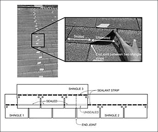
Figure 1: Location of partial unsealing for three-tab (left) and laminate (right) shingle systems
As shown in Figure 1, partially unsealed three-tab shingles (shingle 3 in the figure) were unsealed one-half the tab width on the tab bonded over the end joint of the course below (shingles 1 and 2 in the figure). Figure 1 also shows partially unsealed laminate shingles (shingle 3 in the figure) lacked adhesion from the edge of the strip to the end joint of the course below (shingles 1 and 2 in the figure). The length of the offset distance between shingle courses controlled the lost adhesion's length, and the alignment of the offset end joints controlled the lost adhesion's location. Interestingly, the spatial patterns produced when partially unsealed shingles are marked on the roof (see Photo 2) align with patterns repeatedly observed in post-storm damage reports of asphalt shingle roof systems (see Photo 3).
A roof system's service age was an apparent factor in the occurrence and amount of partially unsealed shingles. Roof systems less than four years in service did not have partially unsealed shingles. When comparing the results from the 27 roof surveys in Florida, a statistically significant difference in the mean total quantity of unsealed shingles on a given roof was established between roofs aged 0-6 years and those aged 7-13 years and 14-20 years. Therefore, the mean percentage of unsealed shingles on a given roof increases with age. On one three-tab asphalt shingle roof system in service for more than 20 years, nearly 86 percent of the shingle strips were partially unsealed—equating to 1,600 of the 1,870 shingle strips installed on the house.
The cause of partially unsealed shingles is being investigated. Clues from the service-age statistics, locations and failure planes indicate the effects of natural weathering are responsible for partially unsealed shingles installed in a roof's field. Installation error was not considered a factor as a result of the observed consistency of unsealed locations among roof systems across a myriad of shingle products and locations in Florida.
Cohesive fractures in the sealant strips were observed on all partially unsealed shingles, indicating the shingles originally were fully adhered along their complete length before losing adhesion along a partial length. An analysis of surface wind fields for historical tropical cyclones using H*Wind, the National Oceanic and Atmospheric Administration's Hurricane Research Division's Real-Time Hurricane Wind Analysis System, ruled out the possibility peak near-roof wind speeds had exceeded product approval tests, such as ASTM D3161, over time since the shingles' installation.
As typically installed, asphalt shingles are offset between courses; therefore, the sealant strip is lapped over two shingle strips when fully adhered after installation. Unsealing occurs near the end joint of the shingle course below (see Figure 1). Given the observations during the roof surveys, we believe long-term thermal cycling of shingled roof systems is the primary cause of partially unsealed shingles. Materials change dimension as their temperatures fluctuate in response to changes in ambient conditions.
Although likely minutely relative to a shingle strip's total dimension, diurnal temperature cycles will induce diurnal dimension change cycles in the shingles. As the sealant strip is lapped over two shingles, expansion and contraction of each shingle will exert an opposing stress on the sealant strip bond to the course above. Long-term cyclical applications of stress combined with the likely loss of flexibility in the sealant strip material itself over time can lead to a cohesive fracture of the sealant strip on the shorter length of bonding. This proposed mechanism is a working theory, and research is continuing to determine the cause of partially unsealed shingles and method to remedy the problem in existing and new roofing products.
Although partially unsealed shingles may retain their water shedding function, the results of the wind tunnel tests at the University of Florida and the IBHS Research Center demonstrated the existence of partially unsealed shingles makes the shingle roof system more likely to suffer wind-induced damage. Test results from the IBHS study catalogued wind-induced damage to shingles in the tested roofs' fields initiated from unsealed shingles that existed before the wind test, as well as shingles at eave and rake roof locations that pulled through edge fasteners. Shingles that were fully sealed before the wind tests remained fully sealed and undamaged throughout the tests unless they were damaged by adjacent pre-wind unsealed shingles lifting or eave and rake shingles that pulled through fasteners.
Wind tunnel results at the University of Florida indicate partially unsealed shingles are more vulnerable to wind-induced damage because the force exerted on a partially unsealed shingle was measured greater (by more than a factor of two) than the force exerted on an equivalent, fully sealed asphalt shingle and the force predicted by ASTM D7158.
The findings from this research demonstrate partially unsealed shingles occur on field locations of residential buildings; such shingles are vulnerable to wind-induced damage and surrounding shingles also are more vulnerable to wind-induced damage.
Furthermore, based on the findings of this research, there is a high degree of confidence that partially unsealed asphalt shingles installed in a roof's field significantly contribute to wind damage.
Hip and ridge
In addition to shingles installed in a roof field, the presence of adhesion on hip and ridge shingles was assessed during 27 roof surveys in Florida. All inspected roof systems contained unsealed hip or ridge shingles. Unlike partially unsealed shingles in a roof field with cohesive failures in the sealant strip, unsealed hip and ridge shingles had adhesive failure planes between the sealant strips and overlying hip or ridge shingles. The adhesive failures indicate the material was either poorly sealed or never adhered at the time of installation. A majority of unsealed hip and ridge shingles was unsealed at the downslope edges and sealed where the shingles folded over the roof line (see Photo 4).
Given the adhesive failure plane and lack of adhesion at the shingle edge, the cause of unsealed hip and ridge shingles is most likely related to the installation method used throughout the roofing industry. Standard hip and ridge shingles originate as flat strips of material, pre-purchased as hip and ridge products or made from three-tab shingle strips. Installers wrap the shingle over the hip or ridge line and place one fastener on either side of the shingle, just above the exposure. The edges of a hip and ridge shingle are less likely to be adhered because they tend to reorient their folded geometry to their original flat state.
Similar to unsealed shingles in a roof field, the consequence of unsealed hip and ridge shingles in high winds was demonstrated during wind tests at the IBHS Research Center. Eight of the 17 roofs were hip-style roofs containing hip and ridge shingles. All eight hip roofs contained partially unsealed hip shingles before the wind test, and all unsealed hip shingles exhibited the same adhesive failure plane on shingle edges.
During wind testing, blow-off of hip shingles initiated from partially unsealed shingles and progressed up the slope of the hip line as the test continued and wind speeds increased. Post-test analysis of the damage progression showed wind flow entering under the hip shingle's unsealed edge induced lifting at the leading edge. Once lifted, drag force on the shingle increased to the point where the entire shingle blew off the roof, leaving the next course hip shingle vulnerable to blow-off. The end results of hip roofs subjected to the three wind directions used in this test are shown in Photo 5.
For roofing professionals, ensuring adhesion at the edges is critical for wind-resistant hip and ridge shingles. Hand-sealing the edges of the shingle as per manufacturer or industry specifications will provide installers with the added security of full adhesion, especially if the ambient weather is cold. Furthermore, ensuring the underlayment is properly lapped over the hip or ridge joints and free of cuts to the material will provide a continuous moisture management plane if one or more sections of the hip and ridge shingles are lost to wind.
Eave and rake details
Eave and rake shingles are among the most common locations of wind damage to asphalt shingles. Post-hurricane reports from the Federal Emergency Management Agency (FEMA) typically cite improper installation methods as the primary cause of damage, yet not much is known about the wind resistance and failure mechanisms of eave and rake edge details. As part of the tests at IBHS, starter strips were installed on all eaves with a 1/2-inch-long overhang from the drip edge metal on eaves and rakes.
The Asphalt Roofing Manufacturers Association's (ARMA's) 2006 Asphalt Roofing Residential Manual specifies fasteners be placed about 1 inch from the rake and 1 1/2 to 3 inches from the eave. Eave and rake shingles installed with fasteners located within ARMA's specifications performed much better than those with fasteners located beyond the specified distance.
Pull-through of the eave starter-strip shingles and rake-edge shingles over attachment points was observed on nearly all roof systems. Pull-through was attributed to unintentional placement of nails up to 5 inches from the eave and rake edge—beyond the 1 1/2- to 3-inch distance specified by ARMA. Photo 6 shows the most significant damage occurring on a test roof—initiated by the pull-through of a corner shingle over an edge fastener placed 4 inches from the rake and 5 inches from the eave. As wind speeds increased, shingle blow-off progressed toward the roof field.
Conclusion
We strongly recommend roofing professionals place fasteners into starter strips on eave- and rake-edge shingles within manufacturer or industry specifications. The closer a fastener is placed to the roof edge, the lower the wind load exerted on the fastener.
Moreover, roofing professionals should minimize the shingle overhang length beyond roof edges as much as possible. Length reduced from the overhang will reduce the wind force on the edge shingle. Additional wind resistance at rakes and eaves may be gained by the application of asphalt roofing cement along rakes and eaves. For guidance, refer to FEMA's Technical Fact Sheet No. 73.
Craig R. Dixon, Ph.D., is a forensic structural engineer at SBSA Inc., Golden, Colo. Kurtis R. Gurley, Ph.D.; Forrest J. Masters, Ph.D., P.E.; and David O. Prevatt, Ph.D., P.E., are associate professors at the University of Florida's Engineering School of Sustainable Infrastructure and Environment, Gainesville, Fla.
Tips to ensure wind-resistant asphalt shingle roof systems:
- Check to see whether the edges of hip and ridge shingles are sealed after installation. If not, hand-seal edges following manufacturer or industry specifications.
- Place fasteners on eave starter strips and rake edges within manufacturer or industry-specified tolerance. Placing fasteners nearer the roof edge will reduce the likelihood of pull-through failure when overhung shingles are loaded by wind.
- Reduce shingle overhang from eave and rake edges to the minimum allowed by manufacturer or industry specifications. Reducing edge overhang will reduce the wind load exerted on the shingle.
- Additional wind resistance on eaves and rakes can be obtained by the application of asphalt roofing cement along each detail. Refer to the Federal Emergency Management Agency's Technical Fact Sheet No. 73 for guidance.