In 1998, SPRI published its first edition of ANSI/SPRI ES-1, "Wind Design Standard for Edge Systems Used With Low Slope Roofing Systems." With the incorporation of ANSI/SPRI ES-1 into the International Building Code, 2003 Edition (IBC 2003), compliance with ANSI/SPRI ES-1 became a building code requirement.
Although ANSI/SPRI ES-1 has existed for more than 10 years and been a building code requirement for more than five years, based on questions received by NRCA's Technical Services Section, ANSI/SPRI ES-1 still does not appear to be widely understood. Also, a certain amount of misinformation regarding ANSI/SPRI ES-1 and its implementation has been circulating in the U.S. roofing industry, which further complicates proper understanding.
If you are involved with the design or fabrication of metal roof edge flashings or the design or installation of low-slope membrane roof systems, you need to know about ANSI/SPRI ES-1.
Background
The American National Standards Institute (ANSI) is a Washington, D.C.-based, private, nonprofit organization that serves as administrator and coordinator of a private-sector national standards system referred to as American National Standards. ANSI membership comprises nearly 1,000 companies, organizations, government agencies and institutions; NRCA is an ANSI member.
SPRI is a Waltham, Mass.-based trade association representing the single-ply roofing industry. Its membership consists primarily of manufacturers of single-ply membrane systems and component accessories and raw material providers.
As it applies to ANSI/SPRI ES-1, SPRI is the standard's promulgator and is responsible for its development and maintenance. SPRI has used an ANSI process to develop and maintain ANSI/SPRI ES-1, making it an American National Standard.
ANSI/SPRI ES-1's first edition is designated ANSI/SPRI ES-1-98 (with "-98" designating the year of publication). It was derived from SPRI's "Wind Design Guide for Edge Systems Used With Low Slope Roofing Systems" originally published in 1994. (For additional information regarding the original SPRI guide, see "A review of SPRI's wind design guide for edge systems," June 1995 issue, page 54.)
ANSI/SPRI ES-1-98 is based on ASCE 7-95, "Minimum Design Loads for Buildings and Other Structures." ANSI/SPRI ES-1-98 uses ASCE 7-95's basic wind speed map to determine design wind loads at roof edges.
In 2003, SPRI updated the standard with a designation of ANSI/SPRI ES-1-03. This version is largely similar to the previous edition but was revised according to ASCE 7's 2002 edition (ASCE 7-02). ANSI/SPRI ES-1-03 is the most current edition.
ANSI/SPRI ES-1-03
ANSI/SPRI ES-1-03 consists of eight primary sections, three test methods and a commentary.
Section 1—Introduction provides the standard's scope, which is a design method for metal edge systems used with low-slope roof systems except gutters. The standard focuses primarily on design for wind resistance but also addresses corrosion and metal thickness necessary for satisfactory flatness.
Section 2—General Design Considerations and Definitions provides information regarding roof slope, basic wind speed, special wind regions, building height, roof edge corner regions and perimeters used for design calculations, and coverage. ANSI/SPRI ES-1 is limited to roof systems with slopes less than or equal to 10 degrees (about 2-in-12). The section states metal flashings should provide coverage that extends down the face a minimum of 1 inch below the bottom of a nailer.
Section 3—Exposure provides definitions for Exposure Categories B, C and D based on the surface roughness of terrain surrounding a building for use in wind design calculations. The definitions generally are consistent with—but not identical to—those of ASCE 7-02.
Section 4—Importance Factors provides Importance Factors ranging from 0.77 to 1.15 for use in wind design calculations. The Importance Factors are consistent with those of ASCE 7-02. An Importance Factor of 1.0 is applicable to most building designs.
Section 5—System Requirements provides design requirements for wood nailers used for attaching metal edge flashings. This section indicates wood nailers should be sufficient to resist the design wind-uplift loads determined in Section 7. It also states corners (defined in Section 2) should be designed to resist loads 1.5 times that determined in Section 7.
Section 6—Design Options provides minimum securement for metal edge systems based on testing according to SPRI test methods RE-1, "Test for Roof Edge Termination of Ballasted or Mechanically Attached Roofing Membrane Systems"; RE-2, "Pull-Off Test for Roof Edge Flashings"; and RE-3 "Pull-Off Test for Copings."
Metal edge flashings except copings and gutters should be tested according to SPRI test method RE-2. Except for built-up and fully adhered roof systems, metal edge flashings also should be tested according to SPRI test method RE-1. The standard indicates metal edge flashings' test results should meet or exceed the design wind pressures determined in Section 7.
Copings should be tested according to SPRI test method RE-3. Test results should meet or exceed the horizontal and vertical design wind pressures determined in Section 7.
The standard also indicates attachment of metal edge flashings at corners should be increased by a factor of two to account for increased wind pressures at corners.
Section 7—Design Provisions provides the procedure for determining design wind pressures at roof edges. The formula is indicated as P = GCp x qz x I where:
- P = Design wind pressure expressed in pounds per square foot
- GCp = External pressure coefficient from ANSI/SPRI ES-1's Table 3 (The table is reproduced in the figure.)
- qz = Velocity pressure at the specific roof height
- I = Importance Factor from ANSI/SPRI ES-1's Table 1 in Section 4
For determining qz, ANSI/SPRI ES-1 provides three tables based on exposure (defined in Section 3). Once the specific table is selected (Exposure B, C or D), qz is determined from the basic wind speed based on the building's location and height. The tables provide velocity pressures for basic wind speeds ranging from 85 to 170 mph and building heights from ground level to 500 feet.
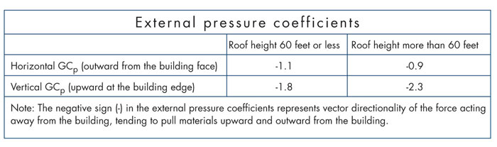
External pressure coefficients from ANSI/SPRI ES-1
Section 7 also includes a table (Table 5) that provides minimum thicknesses for satisfactory flatness of galvanized steel, cold-rolled copper, formed aluminum and stainless steel. Also, information regarding metal's galvanic compatibility and resistance is provided, including the statement: "Copper shall not be used in combination with steel, zinc or aluminum. Only copper fasteners shall be used with copper."
Section 8—Appliances provides guidance that any attachments to metal edge flashings such as lightning rods, signs and antennae that penetrate metal flashings should be eliminated or isolated to prevent galvanic reaction and otherwise compromise the effectiveness of roof edge-metal flashings.
SPRI test methods
As mentioned, ANSI/SPRI ES-1 provides three test methods for determining edge-metal flashings' wind resistances.
RE-1 tests edge-metal flashings' ability to restrain unadhered roof membranes at roof perimeter edges. This test is required for ballasted and mechanically attached membrane systems but not for built-up or fully adhered membrane roof systems or systems using an alternative method for perimeter attachment at roof edges.
RE-2 tests resistances to horizontal (outward from the building face) loads for gravel stops and fascias.
RE-3 tests copings' resistances to horizontal (outward from the building face) and vertical (upward at the building edge) loads.
Code adoption
IBC 2003 states: "1504.5 Edge securement for low-slope roofs. Low-slope membrane roof systems metal edge securement, except gutters, installed in accordance with Section 1507, shall be designed in accordance with ANSI/SPRI ES-1, except the basic wind speed shall be determined from Figure 1609."
IBC 2003's reference to using the basic wind speed map from Figure 1609 of the code rather than ANSI/SPRI ES-1-98's basic wind speed map is necessary because the code's Chapter 16—Structural Loads is based on ASCE 7-02. ANSI/SPRI ES-1's basic wind speed map is based on ASCE 7-95 and is slightly different from the map in ASCE 7-02.
In IBC 2006 and IBC 2009, ANSI/SPRI ES-1-03 is referenced and the specific code language is: "1504.5 Edge securement for low-slope roofs. Low-slope membrane roof systems metal edge securement, except gutters, shall be designed and installed for wind loads in accordance with Chapter 16 and tested for resistance in accordance with ANSI/SPRI ES-1, except the basic wind speed shall be determined from Figure 1609."
Using IBC 2006 and IBC 2009, design wind loads need to be determined using the codes' Chapter 16—Structural Loads, not ANSI/SPRI ES-1-03's design wind load determination procedure in Sections 2, 3, 4 and 7. Chapter 16 of IBC 2006 and IBC 2009 are based on ASCE 7-05. ANSI/SPRI ES-1-03 is based on ASCE 7-02.
Also, the International Code Council, which publishes the IBC, has acknowledged ANSI/SPRI ES-1-03's definitions of exposure categories somewhat differ from those of ASCE 7-05, IBC 2006 and IBC 2009. As a result, ANSI/SPRI ES-1-03's design wind load calculation procedure may produce different results than those the code requires.
Because of this, it is important that if you use either edition of ANSI/SPRI ES-1, you should realize the code does not adopt the standard in its entirety. When using IBC 2006 or IBC 2009, design wind loads should be determined in accordance with the code, not ANSI/SPRI ES-1.
Additional concerns
NRCA has several additional concerns regarding ANSI/SPRI ES-1.
ANSI/SPRI ES-1-03's requirement in Section 6 for increasing the fastener densities in corner regions by a factor of two to address higher wind-uplift pressures at corner regions is questionable. For wood blocking used at attached metal edge flashings at the same corner region locations, the standard's Section 5 provides a requirement that the attachment be increased by a factor of 1.5. This difference in factors between the edge-metal flashing and wood blocking used to support it is irrational because the identical loads act on both components.
Also, though increasing the fastener densities at corners may be appropriate if an edge-metal flashing's tested failure mode is fastener failure (breakage or pullout), doubling the fastener density will do little to increase an edge-metal flashing's resistance at corner regions where its tested failure mode is in flexure (deformation or bending). Based on NRCA's experience with ANSI/SPRI ES-1, flexural failure during testing is far more common than fastener failure. Although the addition of a simple multiplication factor may be convenient from a calculation and design standpoint, it does not adequately provide wind resistances for edge-metal flashings used in corner regions.
Also, ANSI/SPRI ES-1 does not require—nor does it even suggest—the use of a safety factor when comparing tested resistance values derived from RE-1, RE-2 and RE-3 to design wind loads. Use of such a safety factor is commonplace in structural design to account for anticipated variances in loading, testing, materials and application.
A safety factor of 1.67 typically is applied in the design of light-gauge steel and aluminum used for metal panel roof systems. A safety factor of this magnitude is provided for in the American Iron and Steel Institute's "North American Specification for the Design of Cold-formed Steel Structural Members" (AISI S100) and the Aluminum Association's "Aluminum Design Manual: Part 1—A Specification for Aluminum Structures, Allowable Stress Design and Part 1B—Aluminum Structures, Load and Resistance Factor Design" (ADM1), both of which are recognized in the IBC.
On this basis, it appears using a safety factor of 1.67 is appropriate for steel or aluminum metal edge flashings where bending is the controlling failure mode. For other situations or other metals, a larger safety factor may be appropriate.
Industry implementation
NRCA is aware of many instances where roof system designers incorporate ANSI/SPRI ES-1 into project specifications and contracts by including a relatively simple, straightforward statement such as " … edge-metal flashings shall comply with ANSI/SPRI ES-1 … ." However, based on the manner in which IBC has incorporated ANSI/SPRI ES-1 and the standard's shortcomings, such a statement is inadequate in most instances.
Because the code does not adopt ANSI/SPRI ES-1 in its entirety, NRCA recommends roof system designers determine design wind loads for edge-metal flashings according to the code. This calculation is largely similar to the calculations for determining the design wind loads and requirement resistances for roof systems. Then, the design wind loads at the roof edge should be used to determine the specific resistances that are necessary from RE-1, RE-2 or RE-3 as appropriate based on the specific edge-metal flashing type used.
Also, NRCA recommends designers include an appropriate safety factor in their wind-resistance calculations for roof edge-metal flashings. NRCA suggests a minimum safety factor of 1.67 be applied to steel or aluminum edge-metal flashings. This is consistent with AISI S100 and ADM1. For edge-metal flashings constructed of other metals, NRCA suggests a larger safety factor be considered.
NRCA also recommends designers account for higher design wind loads for edge-metal flashings in corner regions by methods in addition to simply doubling fastener density. One suggestion is to use edge-metal flashings with higher resistance loads than is required. Using ANSI/SPRI ES-1's factor of two methodology, specifying tested resistances two times greater than the design wind loads may be prudent.
To account for the code's design wind load method, adding an appropriate safety factor and properly addressing higher design wind loads at corner regions, NRCA recommends designers clearly include the specific tested resistance loads that are needed for the particular perimeter edge-metal flashings being designed.
Looking forward
Although ANSI/SPRI ES-1 has existed for more than 10 years, its implementation is somewhat complicated and not as straightforward as it could be.
NRCA hopes the conflicts between editions of ANSI/SPRI ES-1 and the code's adoption of ASCE 7 can be resolved in future editions of ANSI/SPRI ES-1.
Also, NRCA hopes SPRI properly addresses the issues of using a safety factor and higher design wind loads in roof perimeter edge metal's corner regions in future editions of ANSI/SPRI ES-1.
Addressing these issues will go a long way toward better understanding and proper use of ANSI/SPRI ES-1, which ultimately will improve performance of metal roof edges.
Mark S. Graham is NRCA's associate executive director of technical services.