Before the development and implementation of comprehensive building codes, it was common practice for rooftop equipment to be installed without being firmly attached to a building's structure. The thinking was the weight of an HVAC rooftop unit would be sufficient to keep a curb and the rooftop unit on top of a building. However, recent research into the effects of natural disasters has shown that to resist significant seismic and wind loads, rooftop units must be firmly restrained from moving off their curbs, and curbs must be attached to a building's structure. This research is changing the way curbs are designed, built and installed.
Many U.S. jurisdictions require a licensed engineer to certify that curbs and restraints meet the requirements of applicable building codes. The process by which curbs are now designed can be summarized in three steps.
First, a roof curb designer must determine the governing building code for a particular project. This information is typically provided in the mechanical or structural sections of project specifications. The designer should also be aware of any project requirements that are more stringent than those listed in the building code.
If the project specifications do not include an applicable building code, the designer can determine it by contacting the building department that has jurisdiction in the area where the building is located.
Once an applicable building code is identified, a designer's second step is to determine the seismic- or wind-load design force a rooftop unit and curb are required to withstand. Building codes commonly adopted in the U.S. provide step-by-step procedures for determining design force. A design force may be a result of seismic activity or wind load depending on the project location. In areas of the U.S. where it is not intuitively clear which load is greater, the designer should perform both calculations and design curb and restraints accordingly.
A designer's third step is to determine the requirement for attachment of rooftop equipment to a curb and the curb to a roof.
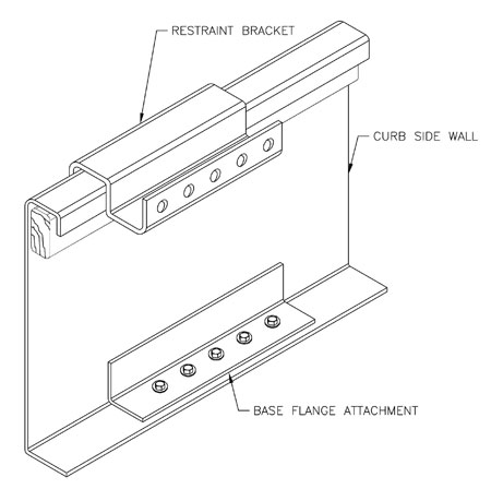
Figure 1: A section view of a curb with equipment restraints and attachment to a building's structure
Once the design load on the rooftop equipment is calculated, the designer uses static analysis to ensure the load is safely transmitted through the equipment base into the equipment support. The method of attachment between the rooftop equipment and curb must be sufficient to keep the equipment in place while resisting tension, shear, moment and uplift forces generated by the design force acting on the rooftop equipment. A curb must be designed and manufactured with the ability to safely transfer these forces into a building's structure. A section view of a curb with equipment restraints and attachment to a building's structure is shown in Figure 1.
A project's mechanical or structural engineer must be aware of the loads that will be imposed on a building's structure by rooftop equipment through a curb.
Building codes
Seismic- and wind-load-related building codes provide a uniform method for determining seismic- and wind-induced forces for any location. The forces must be determined with enough accuracy to ensure safe and economical design. Different regions of the U.S. have adopted standard codes and modified applicable portions of model codes to fit their particular needs. Two examples of such codes are the International Building Code (IBC) and Uniform Building Code (UBC).
IBC
IBC was originally prepared in 2000 by five drafting subcommittees appointed by the International Code Council. The subcommittees included representatives from Building Officials and Code Administrators International Inc., International Conference of Building Officials and Southern Building Code Congress International Inc. Their intent was to draft a comprehensive set of regulations for building systems consistent with and inclusive of the scope of existing model codes.
Forty-seven states and the District of Columbia have adopted IBC as their governing building code. Because IBC is emerging as the dominant code for seismic- and wind-load design issues, an explanation of design force determination is necessary.
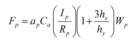
Figure 2: This equation can be used to determine the seismic design force on a building's mechanical components and systems.
IBC 2006's Section 1615 provides general procedures for determining maximum considered earthquake (MCE) ground motion. IBC 2006's Section 1621.1 refers to ASCE 7, "Minimum Design Loads for Buildings and Other Structures" for the seismic design force (Fp) on mechanical components and systems. Fp is the force exerted at the component's center of gravity and distributed relative to the component's mass distribution. Fp can be determined by using ASCE 7-05, Equation 13.3-1, as shown in Figure 2.
Although the full details of all variables used in this formula are beyond this article's scope, four key pieces of information are required to complete curb and restraint design, which follow:
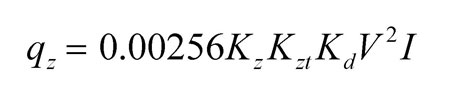
Figure 3: This equation can be used to determine the design wind force on rooftop equipment.
IBC 2006's Section 1609 requires that wind loads on buildings or structures be determined in accordance with ASCE 7. The design wind force on rooftop equipment is calculated according to ASCE 7, Section 6.5.15, "Design Wind Loads on Other Structures." The equation for wind-load design force (Fw) is shown in Figure 3.
Key pieces of information a designer must have include the following:
UBC
UBC was first issued in 1927 by the International Conference of Building Officials and was previously the most widely used building code in North America. Although California is in the process of adopting IBC, the seismic design provisions of the current California Building Code are based on UBC.
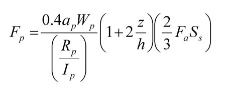
Figure 4: This equation can be used to determine the design lateral force for a building's nonstructural components.
UBC classifies earthquake hazard on a scale from zero (least hazardous) to four (most hazardous). These values are used to determine the strengths of various components of a building required to resist earthquake damage. UBC 1997 is the most recent edition and specifies a design lateral force (Fp) for nonstructural components as shown in Figure 4.
Information required to complete the design of roof curbs and restraints in accordance with UBC 1997 includes:
Static analysis
Once the design load is determined, static analysis is used to ensure equipment will not move during an earthquake or high wind speeds. The forces generated by the difference in accelerations between the equipment's center of gravity and a building's roof must be balanced by reactions at the curb and restraints. The sum of the forces and moments generated between the equipment and equipment support, as well as between the equipment support and building structure, must equal zero. A typical free-body diagram of a static analysis is shown in Figure 5.
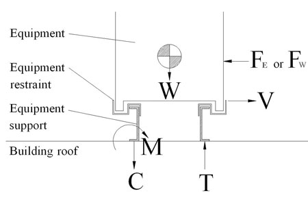
Figure 5: A typical free-body diagram of a static analysis
A licensed engineer uses sound engineering principals and industry-accepted safety factors to perform a static analysis. Detailed drawings of the curb and equipment restraint are used with known material properties and shape factors to verify that allowable stress values are not exceeded in the curb, unit restraints or attachment hardware. The result of this analysis will be a seismic- or wind-load-rated assembly that will safely handle the design forces on a rooftop unit. Restraint brackets are used to provide a positive attachment between a unit and curb, and the curb can be attached to a building's structure using welds, bolts or anchors through holes in the curb base flange. The rooftop unit/curb assembly is, therefore, designed to provide a continuous load path from the unit to the building's structure.
Know the requirements
By following recent building code requirements, a curb can be designed to resist the forces expected from a seismic- or wind-load event. A rooftop unit that resists these forces will remain firmly attached to a curb, and the curb will stay attached to a building's structure, reducing wind and water damage to the building's interior and maintaining functionality of the rooftop unit.
Paul Selman is a mechanical engineer for Thybar Corp., Addison, Ill.


COMMENTS
Be the first to comment. Please log in to leave a comment.