
Recently, storms of increasing intensity have been occurring worldwide. In an Environment & Energy News article republished in Scientific American at the end of the 2022 hurricane season, author Chelsea Harvey noted: “even weak hurricanes are getting stronger as the climate warms.” We in the roofing community would be wise to take note and carefully consider how we can better protect roof corners and edges.
Following the ES-1 test methods can be a solution to some known vulnerable roof system areas. The test methods were developed to assist designers and installers with providing wind-resistant edge-metal systems on low-slope membrane roof systems. Wind tunnel testing of full-scale systems is another approach that can uncover vulnerabilities and failure modes that ES-1 testing can’t capture.
What is ES-1?
ES-1 refers to ANSI/SPRI/FM 4435 ES-1, “Test Standard for Edge Systems Used with Low Slope Roofing Systems.” The latest edition was released in 2022 though the standard first was released in 1998 as ANSI/SPRI ES-1-98. It was first referenced in the International Building Code,® 2003 Edition and remains in subsequent editions. In 2011, it merged with FM Standard 4435, “Approval Standard for Edge Systems Used with Low Slope Roofing Systems.”
Understanding the interaction of ES-1 with the building code is important for designers and contractors. In IBC 2021, the standard is referenced in Section 1504.6, which also calls for edge metal to be designed for wind loads in accordance with Chapter 16. Chapter 16, in turn, references ASCE 7-16, “Minimum Design Loads and Associated Criteria for Buildings and Other Structures.” In IBC 2021, “metal edge systems,” except gutters and counterflashings, must have ES-1-tested edge metal on all built-up, polymer-modified bitumen and single-ply roof systems with slopes less than 2:12.
As states and jurisdictions adopt IBC 2021, more newly installed roofs will fall under the umbrella of the ES-1 standard.
ES-1 test methods
ES-1 is composed of three test methods. The first, RE-1, addresses a roof covering being pulled at a 25-degree angle from the edge metal that serves as its securement point. The left-hand graphic in Figure 1 shows how the test is conducted in the lab, and the right-hand graphic shows how we can understand its relevance in a real-world scenario.
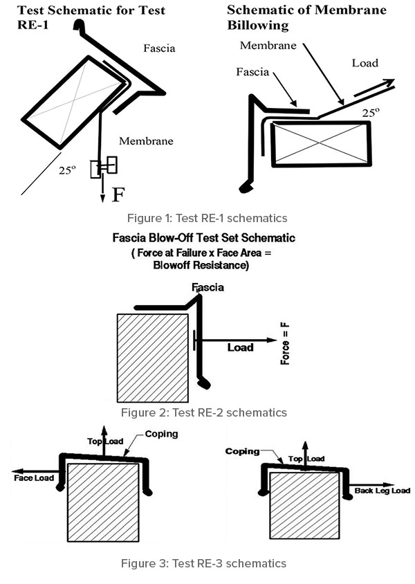
RE-2, shown in Figure 2, simulates horizontal wind load pulling off a fascia, gravel stop or flat perimeter edge metal and, by inclusion, the ability of a continuous cleat to prevent this pull-off.
RE-3 in Figure 3 is composed of two tests of metal copings. The first tests the front leg and top simultaneously, and the second tests the top and back leg simultaneously.
Importantly, ES-1 tests a specific geometry of edge metal, and the size and spacing of fasteners that hold it onto a building.
There are things the three ES-1 tests do not cover. For example, they do not govern the design of the blocking, cladding or other material to which the edge metal is affixed nor do they address gutters. Designers need to reference the appropriate section of the building code in effect to determine the loads to be resisted by these building elements and design overall roof-to-wall construction and load paths accordingly.
The article “Small components, big effects,” in Professional Roofing’s November 2008 issue, stated: “A cleat’s gauge is critical to edge-metal system performance” and recommended “generally, cleats should be one gauge heavier than the edge metal.” ANSI/SPRI ED-1 2019, “Design Standard for Edge Systems Used with Low Slope Roofing Systems” makes this same general recommendation.
Note sheet metal gauges are even-numbered. For example, one might use a 24-gauge coping with a 22-gauge cleat. James Kirby, building science, industry relations and compliance architect for Siplast, Irving, Texas, and one of this article’s authors, echoes this recommendation and suggests cleats two gauges greater than the edge metal they engage can be appropriate.
Critical components
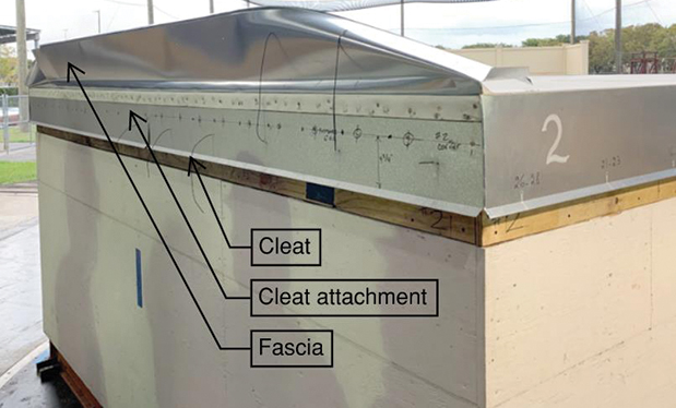
NRCA has found cleat deformation and cleat disengagement from the hemmed edge of fascias and copings is a common cause of failure mechanism in ES-1 testing. Laboratory tests conducted by the authors at the Wall of Wind Experimental Facility at Florida International University as part of the Wind Hazard and Infrastructure Performance Center show how crucial it is to have continuous engagement of a cleat.
As part of a team of scholars and industry partners forming the Wind Hazard and Infrastructure Performance Center, we conducted research to understand how different edge-metal configurations and fastening locations perform in high winds. We completed a series of full-scale tests in the WoW at FIU in February 2022. The WoW has an array of 12 fans that can produce wind speeds up to 157 mph.
We tested four edge-metal systems using different combinations of cleat and fastener locations. Each system was tested by constructing a roof corner with edge metal extending along two sides of a test platform measuring 11 feet wide by 11 feet deep by 6 feet high. The sides met at the corner and were fastened in one of the four configurations.
Because a primary intent of this research was to determine whether fastener placement for a cleat affected wind resistance capacity, mitred corners were intentionally not used. It was presumed the use of a mitred corner would have significantly strengthened each of the tested configurations to the level that the intent of the research would not have been met given the size of a mitred corner relative to the size of the test deck.
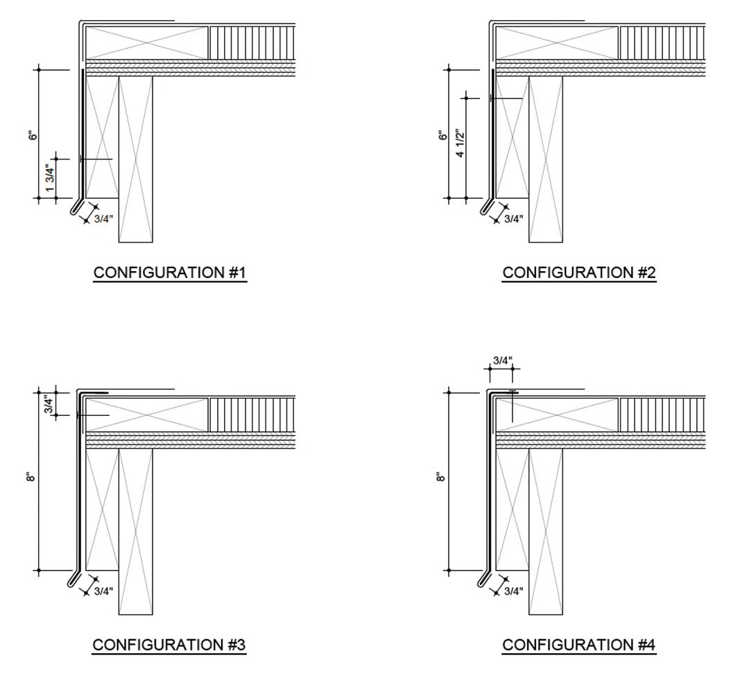
In each edge metal system tested, an 8-inch, 24-gauge steel fascia was fastened into 2- by 6-inch wood blocking through the edge metal’s 4-inch horizontal flange. The drip edge of the fascia measured ¾ of an inch. Figure 4 details the test configurations.
All cleats were 22-gauge steel and positioned and fastened in the following configurations:
- Configuration 1: 6-inch cleat fastened 1¾ inches above the drip edge
- Configuration 2: 6-inch cleat fastened 4½ inches above the drip edge
- Configuration 3: 8-inch L-shaped cleat fastened ¾ of an inch downward from the cleat’s top
- Configuration 4: 8-inch L-shaped cleat fastened ¾ of an inch inward from the cleat’s top
The test roof was a simplified version of a typical roof assembly with a 60-mil TPO membrane induction-welded to 1½ inches of polyisocyanurate insulation atop a ¾-inch plywood deck. The edge condition consisted of 2- by 6-inch wood blocking running horizontally around the perimeter and a 2- by 6-inch wood fascia backed by a 2- by 8-inch rim joist oriented vertically to receive the cleat fasteners where applicable (as in Configurations 1 and 2). The edge condition used in this research, though not a typical flush edge condition, was consistent in all configurations, allowing appropriate comparisons between the four configurations, specifically fastener placement of the cleat. It is unknown whether the lack of flush edge blocking had any effect on the wind speeds at failure.
Where failures occurred
For each configuration, we conducted tests starting at 77 mph and ramping up in 8- to 9-mph increments of three minutes each to a maximum wind speed of 134 mph. Pressures were not recorded during failure testing; calculating an equivalent “real-world” pressure for an actual building would not be appropriate.

The FIU study was a comparative test using wind speeds and differing cleat geometries and attachment locations. For the testing, design wind pressures are not determinable. The tests were run with winds at 0, 45 and 90 degrees to the face of the configuration being tested. Failure was defined as detachment and rotation of the cleat and fascia upward toward the roof surface. This research was conducted under specific laboratory conditions, and wind speeds at the point of failure are not necessarily representative of actual field results.
One side of the corner of Configuration 1 failed immediately at 77 mph because the fascia released from the cleat. The cleat had been fastened about ¼ of an inch higher than intended, and this meant less of its leg was engaged with the fascia (see Photo 1). This fascia subsequently was face-nailed in place to allow the test to continue. Configuration 1 was tested again, and the previously unaffected side of the roof sustained winds of 134 mph before failing.
Configuration 2 remained intact up to a wind speed of 134 mph. As with Configuration 1, the cleat disengaged from the fascia. Before failure, the fascia was observed to flutter at the corner of the roof, but neither the fascia nor the cleat bent outward significantly before the fascia completely disengaged (see Photo 2).
Configuration 3 performed similarly to Configuration 2, failing at 134 mph because of cleat disengagement and corner fluttering during the wind speed ramp up; however, there was some minor outward deflection of the cleat before failure (see Photo 3).
Configuration 4 also sustained winds up to 134 mph before it failed. The fluttering in this configuration began at lower wind speeds and outward deformation of the cleat and fascia was more pronounced than in Configurations 2 and 3 because of the lack of fastening of the lower leg of the L-shaped cleat. In Configuration 4, the failure occurred in two ways. Closest to the corner, the cleat disengaged from the fascia and rotated upward. Further from the corner, the cleat and fascia bent upward from the roof edge and disengaged from one another at some point during the failure (see Photo 4).
What we learned
Following the tests conducted at the WoW, we were able to come to several conclusions:
- Nail placement, in these tests, did not affect the results because all the configurations ultimately failed at 134 mph. Rather, the lack of significant cleat engagement was the variable that led to the early, unexpected failure of Configuration 1 at 77 mph. This slight construction error occurred even in the protected, well-controlled environment of the lab has telling implications for what could happen in the field where installation conditions are often far from ideal.
- Counter to industry experience suggesting otherwise, cleats nailed high on the vertical surface or on the horizontal surface (in the case of L-shaped cleats) sustained wind speeds as high as cleats fastened lower on the vertical surface. The main differences between the 6-inch cleats and the 8-inch L-shaped cleats were the L-shaped cleats bent outward by the wind-uplift forces and the cleat itself flipped upward in a portion of the roof edge in Configuration 4, leaving the roof edge vulnerable to water entry.
- If we rely on the test methods found in ES-1, specifically RE-2 that exerts a horizontal force on the front face of a fascia, gravel stop or flat perimeter edge metal, Configurations 3 and 4 were expected to fail at lower wind speeds than Configurations 1 and 2 because the cleats were fastened high. The fact that Configurations 3 and 4 sustained the same wind speeds as Configuration 2 in the wind tunnel test suggests an additional test method could be developed to better predict the wind resistance of edge-metal systems with cleats fastened higher than current designs. Further testing in-situ or on a larger scale could confirm this finding.
- Researchers should look at ”high-nailed” L-shaped cleats more carefully to see whether they work this well in future tests.
- The advantage of an L-shaped cleat is the top leg allows for easy, consistent placement on the roof edge as it relates to the fascia it is securing. Aligning the cleat with the top and front of the roof edge creates a better probability that cleat engagement also will be more consistent than with more common flat cleats. In cases where there is only one layer of blocking at the top of the roof edge, the simplest, most viable fastening point is on the vertical face of the blocking or its horizontal surface. This is the situation tested in Configurations 3 and 4. However, if a viable substrate (such as additional blocking, masonry or metal cladding) is available lower down, installers can choose to fasten L-shaped cleats there instead.

Future considerations
The WoW showed higher uplift pressures in certain areas of the corner zones (within 2 feet of the corner), and this bears further examination. As an industry, we don’t want to underestimate the actual negative pressures on roofs.
The most important finding from the testing is the need for good engagement of cleats with drip edges of fascias (and copings). Even in a carefully controlled experiment such as a laboratory, a small discrepancy in placement of the cleat led to failure at wind speeds well below what was designed.
We encourage the use of L-shaped cleats to reduce risk of misalignment and reduced engagement with edge metal. We also recommend lengthening a cleat’s drip (the portion that engages directly with the drip edge of the fascia and the drip edge itself).
Many specifications and listed edge-metal assemblies call for a ¾-inch leg on the cleat; a longer leg on the cleat might be beneficial but should be tested to verify any benefits. This will allow for slightly more room for error in installation and less risk to designers, installers and building owners. Some designers and building owners may object to the aesthetics of a longer drip edge. If this is the case, we suggest adopting a detail such as the one from NRCA’s ES-1 certification program where an extended flat drip edge and corresponding cleat are used.
Ensure compliance
There are several pathways to ensure edge metal is ES-1-compliant. One way is to go through NRCA’s third-party certification program for sheet metal shops. The sheet metal provided by these companies has been tested and certified by UL Solutions or Intertek Testing Services N.A. These third-party certifiers also conduct audits where they inspect the machinery with which sheet metal is fabricated, verify the mill certificates of the metal that is used and ensure edge metal is appropriately labeled. Specifiers often will require sheet metal furnished by shops with an NRCA Authorized Fabricator Agreement to get this quality assurance.
UL’s Product iQ, Intertek’s SpecDirect directory and FM Approvals’ RoofNav database also provide similar services to help specifiers and installers identify appropriate ES-1-tested edge-metal systems.
Roofing professionals should note the edge metal verified through ES-1 must be installed as tested. No deviations from the method of attachment, including size and spacing of fasteners, or the geometry of the edge metal itself are permitted. This means any unique designs must be tested.
The more we learn by evaluating edge metal using these test methods, the better we can protect against catastrophic loss of life and property caused by roof system failure.
ELIZABETH GRANT is building & roofing science research lead for GAF, Parsippany, N.J.; JAMES KIRBY is building science, industry relations and compliance architect for Siplast, Irving, Texas; and ERICA SHERMAN is residential R&D process engineering manager for GAF.