
To date, little has been published addressing acceptable tolerances and variations for insulation board fastener placement. For this reason, NRCA has conducted and recently completed small-scale laboratory testing of insulation board fastener placement. This research provides useful information about fastener placement tolerances and yields interesting information regarding insulation deflection in uplift testing.
Test apparatus
For this testing, NRCA used field negative pressure uplift test apparatus and ASTM E907, “Standard Test Method for Field Testing Uplift Resistance of Adhered Membrane Roofing Systems,” and FM Global Loss Prevention Data Sheet 1-52, “Field Verification of Roof Wind Uplift Resistance,” test procedures.
Both test methods are similar and provide for affixing a 5- by 5-foot dome-like chamber to the roof surface’s topside and applying a defined negative (uplift) pressure inside the chamber to the test specimen’s exterior-side surface using a vacuum pump. During the test, test specimen deflection inside the chamber is visually monitored and measured to determine whether the specimen passes or is “suspect.”
According to ASTM E907, a specimen is suspect if the deflection measured during the test is 1 inch or more. FM 1-52 states a specimen is suspect if the measured deflection is between 1/4 of an inch and 15/16 of an inch depending on the maximum test pressure; 1 inch if a thin topping board (cover board) is used; or 2 inches if a thin cover board or flexible, mechanically attached insulation is used.
Test setup
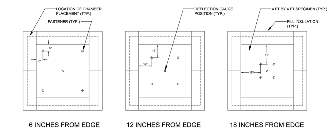
Test specimens consisted of single polyisocyanurate boards measuring 4 feet by 4 feet by 2 inches thick installed over an air retarder layer over a steel roof deck. Four fasteners per board were installed in each of the test specimens in a symmetrical pattern 6, 12 and 18 inches from board edges.
Because the test chamber is wider than a single insulation board, infill insulation was placed around the boards.
The test chamber was placed centered over the specimen with the test’s deflection gauge positioned at a board’s center. The test chamber was placed directly on the insulation boards without a roof membrane in between to eliminate the known variability roof membrane adhesion would have on the test.
Figure 1 shows the test setup.
Results and analysis
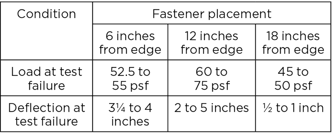
Three tests on separate specimens were conducted for each of the fastener placement locations. Testing was conducted to failure. Failure modes varied, including the insulation board pulling over fastener plates, the insulation board breaking along a knit line and the insulation board breaking at its center. Figure 2 shows the test results.
Manufacturers typically recommend fastener placement be about 12 inches from board edges; however, because of field conditions, fastener placement into immediately adjacent metal deck flanges sometimes is necessary and typically considered acceptable. The 6- and 18-inch locations from the boards’ edges in these tests are intended to represent typical adjacent flute fastener placement locations.
The tests show fastener placement 6 inches from board edges results in an 8.3 to 30% reduction in failure loads compared with 12 inches from board edges. Similarly, fastener placement 18 inches from board edges results in a 16.7 to 40% reduction compared with 12 inches from board edges. These tested values all occur comfortably within the safety factor of 2.0 associated with low-slope membrane roof system wind design.
Particularly noteworthy is the measured deflection values at failure for 6 and 12 inches from board edges are well in excess of the maximum allowable values provided in ASTM E907 and FM 1-52. This indicates these maximum allowable test values have been arbitrarily established and have little technical basis. Also, the variability in the tested values indicates known variability in the test method and normally anticipated material variability.
NRCA acknowledges testing without a membrane adhered to the insulation board’s top surface may affect test results. Thick and heavily reinforced adhered membranes may somewhat restrict an insulation board’s ability to deflect between fasteners during uplift testing. Also, heavily reinforced adhered membranes will result in horizontal (peel) forces being applied to the insulation-to-membrane interface as the insulation board deflects during uplift testing. These peel forces would exhibit themselves as membrane peel or insulation facer sheet delamination failures in uplift testing.
Additional information about tolerances applicable to membrane roof systems is provided in Quality Control and Quality-assurance Guidelines for the Application of Membrane Roof Systems, which is available at shop.nrca.net.
Mark S. Graham is NRCA's vice president of technical services.
@MarkGrahamNRCA
This column is part of Research + Tech. Click here to read additional stories from this section.


