
The fundamental purpose of a roof assembly is to keep water from entering a building through the roof. Low-slope roof assemblies, when properly designed and constructed, perform this function well. However, moist air within a building can enter a roof assembly and condense into water. The climate in which a building is located significantly will affect the type, direction of flow and degree of moisture migration and vapor drive that will occur into and out of a building.
Vapor drive from a building's interior to exterior is likely to be strongest when the exterior temperature and relative humidity are low and the interior temperature and relative humidity are high. These conditions will occur most often during winter months in cold climate regions.
Warmer interior air exerts a higher vapor pressure than cooler outside air. Roof assemblies create a barrier between these areas of differing vapor pressures. If a roof assembly is not sufficiently insulated, warm, moist air will rise into the roof assembly and may cool to its dew-point temperature, causing condensation to occur.
There are three primary methods used to prevent moisture from accumulating in low-slope roof assemblies: use of a vapor retarder, ventilation of interior space and self-drying roof assembly design. This article will focus specifically on vapor retarders.
NRCA guidelines
Vapor retarders primarily are used in low-slope roof assemblies to prevent large quantities of moisture-laden air from a building's interior from moving into the roof assembly where condensation may occur. The use of a vapor retarder has been debated in the roofing industry for years. NRCA has maintained a vapor retarder should be considered by roof system designers when the following two conditions are met: the outside average January temperature is below 40 F (4 C) and the expected interior winter relative humidity is 45 percent or greater.
The outside average temperature for a specific location can be determined from historical climatic data compiled by the National Weather Service. Local climatic data also may be available from private weather services, local television or radio meteorologists, or local weather observers. If local historical climatic data are not available, the map in Figure 1 can be used to determine the general regions that have outside average January temperatures below 40 F (4 C).
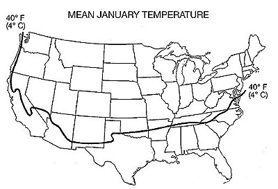
Figure 1: Mean January temperature map
The expected interior winter relative humidity of a particular building can be determined from the design relative humidity value. This value typically is determined by the designer of the building's heating, ventilating and air-conditioning (HVAC) system. For existing buildings, the design interior relative humidity sometimes can be obtained from a knowledgeable building maintenance engineer or whoever maintains the building's HVAC and mechanical control systems.
NRCA's guidelines for determining the need for a vapor retarder have the benefit of simplicity; they are not supported by a great deal of scientifically developed data. Further support for the inclusion of vapor retarders can be obtained from the U.S. Army Corps of Engineers—Cold Regions Research and Engineering Laboratory (CRREL) or American Society of Heating, Refrigerating and Air-Conditioning Engineers (ASRHAE) Inc. In any case, NRCA considers the roof system designer to be responsible for determining whether a vapor retarder is necessary.
For a vapor retarder to perform its intended function, the temperature at a vapor retarder's level must be warmer than the dew-point temperature. Once it has been determined a vapor retarder is to be used, the design temperature at the bottom side of the vapor retarder should be calculated and the design dew-point temperature determined. To ensure the temperature at the vapor retarder remains higher than the dew-point temperature, sufficient insulation amounts must be determined and installed above the vapor retarder to maintain the vapor retarder at a warm enough temperature.
Heat loss
During winter, warm interior air will cool as it passes through or across a roof assembly. The rate at which the air cools depends on the material it is passing through because every building material has distinct thermal-resistance properties. It is a roof system designer's goal to make sure the temperature at the vapor retarder membrane is warmer than dew-point temperature, which, in effect, causes dew-point temperature to occur within the insulation that is installed above the vapor retarder. One method to accomplish this is to graphically illustrate the temperature change.
Graphic method
The temperature gradient, or amount of heat loss, can be illustrated on a roof assembly diagram. The following example is based on a simplified procedure that shows a graphic demonstration of temperature distribution through a roof assembly.
Consider the following example problem: The building in question is a textile mill located in Baltimore. The interior design dry bulb temperature is 70 F, and the interior design relative humidity is 65 percent. Your job is to calculate and illustrate the temperature gradient through a roof assembly composed of a gravel-surfaced built-up roof, 3/4-inch-thick perlite insulation, 2-inch-thick polyisocyanurate insulation, two-ply felt and asphalt membrane vapor retarder, 1/2-inch-thick gypsum board and metal deck.
The first step is to determine the winter interior design dry bulb temperature. This value should come from the HVAC system designer or, if it is an existing building, a knowledgeable building maintenance engineer or whoever maintains the building's HVAC and mechanical control systems. For this example, as mentioned, the winter interior design dry bulb temperature is 70 F.
Next, determine the winter exterior design dry bulb temperature. Design values can be found in Appendix 3—Climate/Design Data of The NRCA Roofing and Waterproofing Manual, Fifth Edition, or in Chapter 27—Climatic Design Information of the 2001 ASHRAE Handbook—Fundamentals. For Baltimore, the winter exterior design dry bulb temperature is 10 F.
Then, draw the roof assembly at a reasonable scale, such as 3 inches equals 1 foot. Next, lay out a temperature scale underneath the drawing. The starting temperature of the scale's left side will be the winter interior dry bulb design temperature. The scale will end on the right side with the winter exterior design dry bulb temperature value. Then, place evenly spaced vertical lines between these two lines to represent 5- and 10-degree increments. (See Figure 2.)
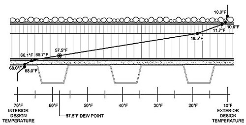
Figure 2: Temperature gradient through a roof assembly
Next, determine the roof assembly's overall R-value. Typical thermal properties of common building materials can be found in the Moisture Control section of The NRCA Roofing and Waterproofing Manual, Fifth Edition, or Chapter 25—Thermal and Water Vapor Transmission Data of the 2001 ASHRAE Handbook—Fundamentals. It is important to note air film exists on a roof assembly's exterior and interior sides. Air film has an R-value that contributes to a roof assembly's overall R-value. Also, there are different R-values for interior and exterior air films during winter and summer. Figure 3 lists the R-values for the example building.
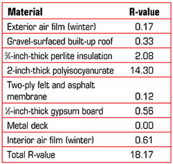
Figure 3: Sample R-values
The next step is to calculate the amount of heat loss occurring at each material using the fundamental heat-loss formula temperature drop =
Ti - [(R/RT) x ?T]
where:
Ti = design inside (interior side) temperature, degrees Fahrenheit
?T = (winter interior design dry bulb temperature) - (exterior design dry bulb temperature)
?T = 70 degrees - 10 degrees = 60 degrees
R = cumulative R-values of materials starting from the interior
RT = R-value of the total assembly
See Figure 4 for calculations for the example building.
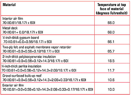
Figure 4: Calculations for the sample building
Then, plot the temperature gradient values for each material on the roof assembly drawing. Note the temperature determined in the previous step is located on the top surface of the material layer. Draw a line from the interior temperature to the next value and continue connecting the plotted temperature values until the line reaches the exterior design temperature as shown in Figure 2.
Next, determine the dew-point temperature. Dew-point temperature can be determined by using a simplified version of the ASHRAE psychrometric chart, which is shown in Figure 5. As previously mentioned, the interior design conditions are 70 F for design dry bulb temperature (design inside temperature) and 65 percent relative humidity (design relative humidity).
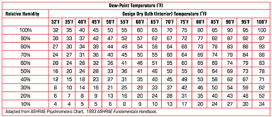
Figure 5: A table version of ASHRAE's psychrometric chart
Along the top of the table, locate the design dry bulb (interior) temperature column, which, in this case, is 70 F. Next, locate the relative humidity row along the left side of the table. The dew-point temperature is at the intersection of the design dry bulb temperature column and relative humidity row. In this case, 65 percent isn't specifically listed as a relative humidity, so you must use linear interpolation between the dew-point values given for 60 percent and 70 percent relative humidity as follows: interpolated dew-point value =
DP1 + RH - RH1 (DP2 - DP1)
RH2 - RH1
where:
DP1 = 55 degrees (dew-point temperature for 60 percent relative humidity)
DP2 = 60 degrees (dew-point temperature for 70 percent relative humidity)
RH = 65 percent
RH1 = 60 percent
RH2 = 70 percent
Finally, locate the dew-point temperature value on the temperature gradient line. If the dew-point temperature falls within the insulation that is placed above the vapor retarder, condensation should not occur on the bottom side of the vapor retarder. If it falls below the insulation, additional insulation is required.
If additional insulation is required, select a new amount of insulation and perform the graphic analysis again to determine whether the dew-point temperature falls within the insulation. Additionally, if the dew-point temperature falls within the upper portion (around the upper one-third) of the insulation, the insulation amount may be able to be reduced as long as the dew point stays within the insulation and the insulation amount meets building code requirements. It is necessary to perform the graphic analysis to determine whether the reduced insulation amount continues to keep the dew point within the insulation.
A word of caution
The graphic method presented in this article is a simplified procedure using theoretical constant values. Actual relative humidity and dew-point temperature values constantly change in typical building environments as the ambient temperature and/or water vapor pressure in the air change. An HVAC system designer typically determines design values to size equipment and for building envelope thermal insulation and water vapor control. These design values most often are based on anticipated maximum extreme conditions. Because the graphic method is just one way to determine whether a vapor retarder will perform its intended function, roof system designers should further substantiate their analyses by using other methods. Additional methods can be found in The NRCA Roofing and Waterproofing Manual, Fifth Edition.
Joan P. Crowe is an NRCA manager of technical services.
Definitions
Design dry bulb temperature, exterior: This is the winter design outside dry bulb temperature. The unit of measurement is expressed as degrees Fahrenheit.
Design dry bulb temperature, interior: This is the design dry bulb temperature of the inside of the building during winter conditions. The unit of measurement is expressed as degrees Fahrenheit.
Dew-point temperature: This is the temperature at which air becomes saturated with water vapor or the temperature at which air has a relative humidity of 100 percent. The unit of measurement is expressed as degrees Fahrenheit.
Dry bulb temperature: This is the temperature of air as measured by an ordinary thermometer. The unit of measurement is expressed as degrees Fahrenheit.
R-value: This represents thermal resistance value as it applies to a specific thickness of a material or construction. Thermal resistance is the mean temperature difference between two defined surfaces of material or construction that induces heat flow through a unit area under steady conditions. In English units, it is expressed as degrees F•ft²•h/Btu.
Relative humidity: This is the ratio of the pressure of water vapor present in a given volume of air to the pressure of fully saturated water vapor at the same temperature. It is expressed as a percentage.