
For several years, the Canadian National Research Council's Institute for Research in Construction has been managing the Special Interest Group for Dynamic Evaluation of Roofing Systems (SIGDERS)—a consortium of manufacturers, building owners, trade associations and researchers. SIGDERS has helped advance the knowledge for the testing and design of mechanically attached flexible membrane roof assemblies in North America. These types of assemblies, composed of flexible sheets (the waterproofing component) and mechanical attachments to resist wind uplift, are used on more than 30 percent of North American low-slope buildings, according to NRCA's 2004 Project Pinpoint. What follows is an explanation of the SIGDERS test protocol and application recommendations based on the testing. The information is based on the paper "A Guide for the Wind Design of Mechanically Attached Flexible Membrane Roofs," co-authored by Tom Smith, president of TLSmith Consulting Inc., Rockton, Ill., and me.
Calculation and evaluation
Determining design wind loads is the first step in designing a roof assembly. Wind loads on buildings are determined in accordance with building codes or standards; in Canada, the National Building Code of Canada 2005 (NBC) is the model code. The reference dynamic pressure for roof covering loads is based on a mean recurrence interval of 50 years. In the U.S., ASCE 7-04 is used. The wind-load calculation procedure for roof coverings can be summarized in six steps:
- Calculation of dynamic pressure
- Definition of the corner zone
- Calculation of external wind pressure component
- Calculation of internal wind pressure component
- Calculation of net wind pressure
- Development of the loading diagram
A roof assembly's wind-uplift resistance is a function of the components used (membrane, seams, fasteners, deck) and their arrangement. Roofing materials manufacturers provide design resistance values for their systems based on uplift testing. It is critical these test methods offer a meaningful measure of a system's uplift performance. To satisfy industry demand for test methods that better simulate actual in-service conditions, SIGDERS developed a new test procedure, which does the following:
- Achieves failure modes that occur under real conditions
- Is easier to apply in the laboratory than existing tests
- Allows for variation in roof system design
- Produces results quickly
- Conforms to local standards
The SIGDERS dynamic testing protocol has five rating levels (A through E); each level consists of eight load sequences with different pressure ranges. Testing begins at level A; if a roof passes A, it advances to B and so on. Based on the SIGDERS test protocol, a national Canadian standard, CSA A 123.21, "Standard Test Method for the Dynamic Wind Uplift Resistance of Mechanically Attached Membrane Roofing Systems," was issued in 2004.
Before CSA A 123.21, there were two static test standards used in North America to assess wind-uplift performance of membrane roof systems (both were based on static testing): FM 4470, "Class I Roof Covers," and UL 580, "Tests for Uplift Resistance of Roof Assemblies."
For design purposes, the sustained resistance an assembly achieves in either static or dynamic testing must be reduced by a safety factor using one of the following equations:
- Allowable design load = test resistance pressure ÷ safety factor
- Required test resistance = allowable design load x safety factor
The safety factor is intended to account for (within reasonable limits) variable material strength of roof assembly components, variability in construction quality and actual wind speed exceeding design values.
Roof system designs should be based on a minimum safety factor of 1.5 for systems tested under dynamic conditions. The higher the safety factor is, the greater reserve strength there is to avoid damage during high-wind events. During the design stage, it is necessary to correlate the design load with the resistance. For a roof to remain intact, the resistance always must be higher than the design load.
Design of components
Mechanically attached roof membranes respond to wind loading differently than other roof coverings. Wind-induced suction repeatedly lifts the membrane between the attachments and causes elongation and billowing (see Figure 1). This can lead to fatigue of the membrane, fasteners, substrate and fastener/deck connection.
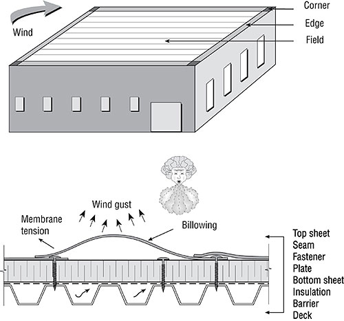
Figure 1: Wind effects on mechanically attached roof systems All figures courtesy of the Institute for Research in Construction
Roof system performance depends on component-to-component resistance to wind uplift. All resistance links must remain connected for a roof system to be durable and remain in place (see Figure 2). Failure occurs when the wind-uplift force is greater than the resistance of any one of the links between membrane, seam, insulation, retarder, plates, fasteners or deck. For example, roof system failure can be initiated when a fastener pulls out from a deck even though the membrane and its seams remain in good condition. In addition, failure can occur when a seam opens. Some recommendations for component application follow.
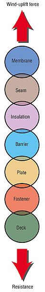
Figure 2: Resistance links of a mechanically attached roof system
Membrane
Certain roof membrane properties (such as tensile strength and tear resistance) influence a roof system's wind-uplift performance. A roof membrane also can tear and pull out from underneath a fastener plate (or batten) because of a lack of clamping force. This failure mode is caused by inadequate fastener plate clamping force and results in membrane tearing at the fastener shank. Loss of clamping force can be caused by the following:
- Insulation creep (the insulation relaxes after fastener applications)
- Inadequate compression resistance of the insulation to prevent overturning of the fastener plate/batten (see Figure 3)
- Insulation shrinkage
- Fastener plate/batten deformation
- Fastener backout
- Localized deformation (steel decks) in the vicinity of the fastener
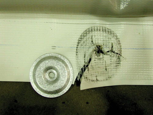
Figure 3: The membrane tear underneath the fastener plate was caused by a lack of clamping force.
Seams
There are two basic types of seams used for mechanically attached flexible membrane roofs. An asymmetrical seam is the most common arrangement for thermoplastic membranes (see Figure 4). Although such a seam can be designed successfully, wind loading causes greater stress to this type than to its symmetrical counterpart.
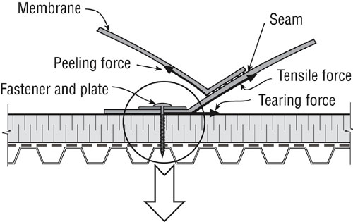
Figure 4: Asymmetrical seam for a thermoset membrane
A symmetrical seam substantially reduces force eccentricity compared with asymmetrical designs because of a reduction of the forces attempting to overturn the fastener plate and rock the fastener shank as shown in Figure 5.
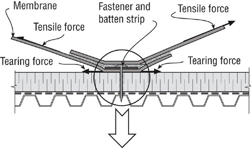
Figure 5: Symmetrical seam for a thermoset membrane
Fasteners
Fastener plates and batten bars maintain a clamping force on a membrane to deter tearing and slippage from under the plate. Fastener plates with barbs provide increased resistance to membrane slippage (see Figure 6). Some fastener plate designs provide resistance to "pop up," which occurs when insulation compresses or a fastener backs out and risks puncturing the membrane. If a plate is an anti-pop-up type, membrane puncture is unlikely, but plate compression still can occur, making a membrane susceptible to tearing at fastening points.
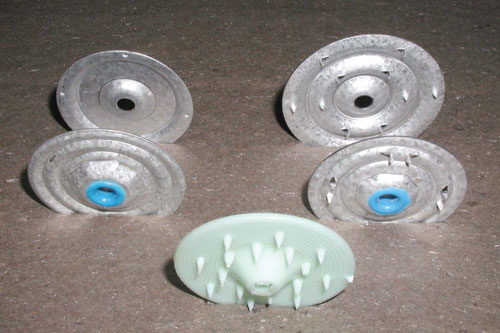
Figure 6: Typical membrane fastener plates
Batten bars distribute loads by providing a clamping force to deter membrane tearing and slippage. They need to be suitably robust to withstand repeated dynamic loading from high-wind events without deforming.
The membrane attachment method significantly influences a mechanically attached roof's wind-uplift performance with fastener thread designs playing a vital role in resistance. Anti-backout fasteners are recommended because of their thread design, which reduces the potential for backout.
The orientation of fastener rows with respect to deck flanges affects the connection of a deck to supporting beam/joists. If membrane fastener rows are perpendicular to the flanges, the deck/support attachment loads are reduced. Therefore, engineers recommend fastener rows perpendicular to the deck flanges (see Figure 7).
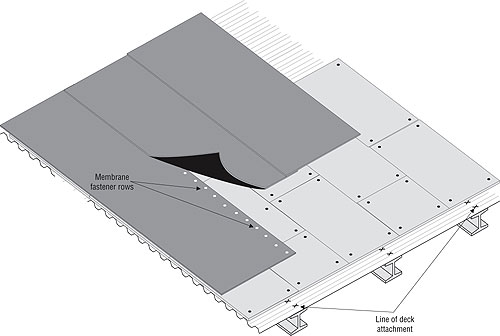
Figure 7: Influence area as a function of fastener row orientation—membrane fastener rows are perpendicular to the deck flanges
Insulation and cover boards
The control of heat movement through a roof system depends almost exclusively on the insulation, which also has an important role in a roof assembly's wind-uplift performance. Although many types of thermal insulating materials are available, polyisocyanurate insulation is used for a majority of mechanically attached flexible membrane roofs.
Thicker insulation requires a longer fastener shank. This can apply a greater rocking force; if this force is sufficient enough to crush the insulation, the rocking of the fastener results in a reduction of the plate's clamping force. The fastener's horizontal rocking movement is reduced when an air/vapor retarder is installed as part of the roof assembly because it distributes the load. When no retarder is used, insulation thickness has minimal effect on the wind-uplift ratings of mechanically attached systems.
Cover boards provide several benefits, including:
- Protecting insulation from mechanical damage caused by traffic loads
- Preventing fastener plates from causing localized crushing of insulation during high winds
- Providing some protection for heat-sensitive insulation boards during torch applications
- Reducing the risk of problems from condensation within the roof assembly
- Protecting the insulation from solvent degradation
- Providing a moisture buffer between the insulation and roof membrane
- Improving fire resistance
Vapor retarders
Vapor retarders limit airflow into a roof system, which reduces energy losses in the assembly. They can reduce membrane flutter and should be used wherever moderate winds are frequent. Vapor retarders commonly are constructed with sheet materials, such as polyethylene. (A two-ply built-up sheet or one-ply modified bitumen sheet also can be used.) When sheet products are used, they are applied directly over the deck. The joints of polyethylene sheets are sealed with tape or sealant before insulation/cover boards are placed and mechanically fastened to the deck. This means the air retarder assembly (insulation boards, fasteners and other components above the vapor retarder) must be designed to resist 100 percent of the design uplift load (adjusted for safety factor).
Although air retarders have many benefits, they can make it more difficult to detect leaks. So a small opening in a roof membrane can go unnoticed for quite a while, resulting in a large area of wet roof insulation.
Deck
Decks and deck attachments are essential features of mechanically attached flexible membrane roof systems. Plywood, wood, plank, concrete or steel are used on roofs with flexible membranes. For roofs with high design uplift loads, a thicker deck and stronger fasteners or denser patterns should be specified to provide added resistance.
The deck attachment of the supporting structure must resist design uplift loads adjusted for the safety factor. It is desirable to use short membrane fasteners that engage the top of a deck's flange to reduce the fastener's rocking movement.
However, when there are multiple layers of insulation or tapered insulation or if a roof is being re-covered, limiting attachment to the top flange can be time-consuming and difficult compared with using fasteners long enough to engage the bottom flange. In this situation, it is better to increase fastener density.
They all work together
The successful design and construction of mechanically attached flexible membrane roofs is a factor in calculating wind forces and ensuring the links between roof elements are capable of resisting them. For membrane roofs, this means selecting a material adequately tested using dynamic loadings simulating in-service conditions.
Bas A. Baskaran is group leader of the Performance of Roofing Systems and Insulation subprogram at the Institute for Research in Construction, which is part of the National Research Council of Canada in Ottawa.