NRCA's online wind-load calculator, Roof Wind Designer, recently was updated to include the 2010 edition of ASCE 7, "Minimum Design Loads for Buildings and Other Structures." The 2010 edition, designated ASCE 7-10, serves as the technical base for wind-load determination in the International Building Code,® 2012 Edition (IBC 2012).
Roof system designers should be aware of some significant changes addressing wind design in ASCE 7-10.
ASCE 7
ASCE 7 is a widely recognized consensus standard method for determining design wind loads on buildings and other structures. ASCE 7 contains separate provisions for the design of major structural elements (referred to as main wind-force resisting systems) and components and cladding (roof systems). Furthermore, wind-uplift loads are determined for three different zones of a roof system's area: field, perimeter and corner.
As mentioned, there are some significant changes in ASCE 7-10. There is a terminology and concept change regarding building usage type. ASCE 7-05, the standard's previous version, refers to an "occupancy" category and wind loads are based on a building's occupancy. ASCE 7-10 refers to a "risk" category and wind loads are based on risk associated with unacceptable performance.
A noticeable modification was the chapter reorganization for wind design. The 2005 edition addressed wind design in one chapter, Chapter 6, while the 2010 edition has six chapters, Chapters 26 to 31. The chapter relevant to roof systems is Chapter 30, which addresses components and cladding. In addition, ASCE 7-10 provides six primary wind design approaches applicable to roof systems, as well as a wind tunnel testing method, compared with three design methods contained in ASCE 7-05.
But the most notable change between the two editions is the wind design calculations. Design wind pressures on roof systems are determined based on a number of considerations, including a specific building's mean roof height and basic wind speed. Also, how to determine basic wind speed and eventually calculate design wind pressures is different between the two editions. Before I explain the changes, it is important you understand the two structural design methods used in ASCE 7.
ASCE 7 provides two design methods for determining minimum building load requirements: allowable stress design (ASD) and strength design. Both methods use a variety of load combinations requiring the use of load factors for each design load type (such as wind, snow or seismic) to ensure the structure's safety under anticipated loading conditions. Generally, roof systems are designed using ASD.
As previously mentioned, the basic wind speed for a building's location needs to be determined to compute its design wind loads. Basic wind speeds are indicated by contours on a map. ASCE 7-05 uses a single basic wind speed map. The wind speeds are peak gusts measured 33 feet above grade in open terrain. Basic wind speed, along with an importance factor (based on the building's occupancy), is used to determine design wind-load pressures. In ASCE 7-05, the wind-load factor for ASD is 1.0, so the design wind-load pressures are multiplied by 1.0.
ASCE 7-10 uses three basic wind speed maps (also based on peak gusts measured 33 feet above grade in open terrain) for different buildings' risk categories. The three maps are designated as follows: Category I (buildings representing a low risk to human life in the event of a failure); Category II (most residential, commercial and industrial buildings); and Categories III and IV (buildings where failure could pose a substantial risk to human life or essential facilities). Most significantly, these maps provide basic wind speeds directly applicable for determining pressures for the strength design method. In addition, the importance factor is eliminated because load factors were applied to the wind speed maps.
To compensate for the switch to strength design-based maps, changes were made to load combinations. Consequently, the strength design wind-load factor was changed to 1.0 in ASCE 7-10 (the 2005 edition used 1.6). Because ASD values commonly are used to determine wind-resistance pressures for roof systems, a roof system designer using ASCE 7-10 may want to adjust the strength design values to ASD values. When doing so, applying a load reduction factor of 0.6 may be appropriate.
Determining wind resistance
To reasonably ensure a roof system's wind-resistance capacity is greater than design loads, engineering and wind-design practices call for safety factors to be applied to roof systems' design wind loads. Safety factors for building materials, components and systems typically vary in magnitude based on a number of factors, including materials used and complexity of building system components. For low-slope membrane roof systems, a minimum safety factor of 2.0 typically is considered appropriate and based on ASTM D6630, "Standard Guide for Low Slope Insulated Roof Membrane Assembly Performance."
To determine a roof system's wind-resistance values for design purposes using ASCE 7-05, multiply the ASD design wind loads by the ASD 1.0 wind-load factor and appropriate safety factor. To determine wind-resistance values for a roof system using ASCE 7-10, multiply the strength design wind loads by the reduction 0.6 load factor and appropriate safety factor.
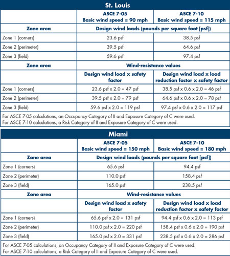
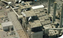
Figure 1: Comparison of 60-foot-high rectangular-shaped office building in two locations
Users familiar with ASCE 7 will notice basic wind speeds generally are higher in the 2010 edition; however, in many cases the design wind loads will be lower and, consequently, so will the wind-resistance values. To illustrate this, Figure 1 compares a 60-foot-high rectangular-shaped office building in two locations.
Roof Wind Designer
Roof Wind Designer is a Web-based application intended to provide a relatively easy way to determine roof systems' design wind loads for many commonly encountered building types. Roof Wind Designer debuted January 2007 and was based on ASCE 7-05. At that time, projects were restricted to buildings having roof slopes equal to or less than 1 1/2:12 (7 degrees). In May 2010, the application was updated to include hip roofs with slopes equal to or less than 6:12 (27 degrees) and gable roofs with slopes equal to or less than 12:12 (45 degrees). The most recent update to Roof Wind Designer includes ASCE 7-10 provisions and allows users to select either ASCE 7-05 or ASCE 7-10.
When selecting ASCE 7-10, the design wind loads determined by Roof Wind Designer are based on Part 2:
Low-rise Buildings (Simplified) of Chapter 30 and, consequently, Roof Wind Designer is limited to the following parameters:
- The mean roof height, h, is less than or equal to 60 feet (h = 60 feet).
- The building is enclosed and conforms to wind-borne debris provisions.
- The building is a regular-shaped building or structure.
- The building does not have response characteristics making it subject to wind loading, vortex shedding, and instability caused by galloping or flutter and does not have a site location for which channeling effects or buffeting in the wake of upwind obstructions warrant special consideration.
- The building has a flat roof = 11/2:12 (7 degrees), a hip roof = 6:12 (27 degrees) or a gable roof = 12:12 (45 degrees).
Roof Wind Designer prompts you to enter data on nine screens identified as follows:
- Select Version—select ASCE 7-05 or ASCE 7-10
- Instructions
- Project Information—input building address and basic information
- Roof Description—input building dimensions, roof configuration, roof slope and whether the building has a parapet
- Building Configuration—select enclosed, partially enclosed or open
- Exposure—select the appropriate exposure category
- Risk Category—select the appropriate risk category
- Basic Wind Speed—a value will appear based on the county selected (it can be overridden)
- Roof Type—select a roof deck type and roof covering type, and it will determine the safety factor
To continue, input data must be provided for every required field. Misinformation, miscalculations, mistakes or changes in the information entered may affect the results, accuracy, reliability and/or other aspects of the summary report.
Once the information has been completed on all screens, the results of the analysis are presented in a report describing the ASD and strength design wind loads for the roof area's field, perimeter and corner zones. It also provides minimum recommended wind-resistance values. The report can be viewed and saved from within the application. It also can be printed and e-mailed as a PDF.
Roof Wind Designer only will apply the safety factor to the ASD values. To determine minimum recommended wind-resistance values using the strength design method, designers will need to determine an appropriate safety factor on their own.
It is important to note Roof Wind Designer determines wind-resistance values using two safety factors. For most roof assemblies, a safety factor of 2.0 is appropriate; however, for a roof assembly with a steel deck and a steel or aluminum metal panel roof system, Roof Wind Designer applies a safety factor of 1.67. This safety factor is recommended in AISI S100, "North American Specification for the Design of Cold-Formed Steel Structural Members," and The Aluminum Association's Aluminum Design Manual, Specification for Aluminum Structures section.
Roof system selection
Once you determine necessary wind-resistance values, start the search for a roof system that will meet the requirements. Roof systems' wind-uplift capacities typically are determined by laboratory testing or engineering analysis. In IBC 2012, three recognized test methods are referenced as code-acceptable methods for determining roof systems' wind capacities: FM 4474, "American National Standard for Evaluating the Simulated Wind Uplift Resistance of Roof Assemblies Using Static Positive and/or Negative Differential Pressures," UL 580, "Tests for Uplift Resistance of Roof Assemblies," and UL 1897, "Uplift Tests on Roof Covering Systems."
FM 4474 is a laboratory test method and serves as the technical basis for FM Approvals' approval designations (1-60, 1-75, 1-90, etc.). FM Approvals indicates a roof system with a 1-60 approval designation is recommended for use when the wind-resistance load is 30 pounds per square foot (psf) or less. A 1-75 approval designation is recommended for use when the wind-resistance load is 37.5 psf or less. And a 1-90 approval designation is recommended for use when the wind-resistance load is 45 psf or less and so forth.
Also, FM Global's Property Loss Prevention Data Sheet 1-29, "Roof Deck Securement and Above-Deck Roof Components," addresses FM Global's recommended guidelines for addressing wind-uplift capacity in Zone 2 (roof area perimeter) and Zone 3 (roof area corners). FM Approvals online approval directory with a list of its approved roof systems and a copy of FM Global's Property Loss Prevention Data Sheet 1-29 can be viewed using FM Approval's RoofNav application at www.roofnav.com.
Underwriters Laboratories® (UL) Inc.'s UL 580 and UL 1897 are the laboratory test methods serving as the technical basis for UL's classifications (Class 30, Class 60, Class 90, etc.) for wind-uplift resistance. UL's classifications indicate a roof system with a Class 30 designation has been tested and found resistant to wind-uplift loads of 30 psf. A Class 60 designation has been tested and found resistant to wind-uplift loads of 60 psf. A Class 90 designation has been tested and found resistant to wind-uplift loads of 90 psf and so forth. UL does not provide specific guidance regarding addressing wind-uplift capacity in Zone 2 (roof area perimeter) and Zone 3 (roof area corners).
Additional information regarding UL's wind-uplift classifications is available on UL's website, www.ul.com, in the Online Certifications Directory by typing "TGIK" in the UL category code field.
Additional information regarding roof systems' wind-uplift capacities also is available by contacting individual roof system manufacturers.
When you evaluate and compare wind-resistance capacities among different roof systems, I encourage you to make comparisons using similar wind-resistance capacity determination test methods. For some identical roof systems, wind-resistance capacity results sometimes vary significantly between test methods.
A useful tool
The latest update to NRCA's Roof Wind Designer allows you to choose between the 2005 and 2010 editions of ASCE 7. This application is an easy-to-use means to determine roof systems' design wind loads and wind-resistance values for many commonly encountered building types. Using this information, you can select appropriately classified wind-resistant roof systems.
Roof Wind Designer was developed in cooperation with the Midwest Roofing Contractors Association and North/East Roofing Contractors Association and is available at no cost. It can be accessed at www.roofwinddesigner.com.
I encourage you to become familiar with ASCE 7-10 because it contains significant revisions to the previous edition, ASCE 7-05. Several changes significantly will affect the wind design of buildings' exterior envelopes, including roof systems. ASCE 7-10 is available from ASCE in print, CD and downloadable electronic file formats at www.asce.org.
Joan P. Crowe, AIA, is an NRCA director of technical services.
Did you know?
Since November 2006, there have been 4,170 registered users of Roof Wind Designer. Those users have created 10,030 projects with the software. Florida and Texas have the most projects—2,159 and 1,115, respectively.