NRCA recently published The NRCA Roofing Manual: Metal Panel and SPF Roof Systems—2012. This volume, part of The NRCA Roofing Manual, provides new and updated best-practice guidelines applicable to metal panel and spray polyurethane foam (SPF) roof systems and replaces The NRCA Roofing Manual: Metal Panel and SPF Roof Systems—2008.
Currently, The NRCA Roofing Manual contains the following volumes: The NRCA Roofing Manual: Metal Panel and SPF Roof Systems—2012; The NRCA Roofing Manual: Membrane Roof Systems—2011; The NRCA Roofing Manual: Architectural Metal Flashing, Condensation Control and Reroofing—2010; and The NRCA Roofing Manual: Steep-slope Roof Systems—2009.
Following is an overview of changes and new information introduced in The NRCA Roofing Manual: Metal Panel and SPF Roof Systems—2012.
Manual development
The 2012 volume, similar to NRCA's other technical publications, was developed by practicing roofing professionals who serve on NRCA committees. NRCA's Manual Update Committee primarily was responsible for developing the 2012 volume. NRCA's Technical Operations Committee and Executive Committee provided essential input and guidance to the Manual Update Committee and periodically reviewed and suggested revisions.
In developing the 2012 volume, NRCA maintains its longstanding position that the manual represents time-tested, best-practice guidelines for roof system installation.
NRCA's approach generally is at a somewhat higher level than building codes' minimum requirements and is consistent with or at a higher level than manufacturers' recommendations. Building codes provide minimum legal requirements for construction, and manufacturers' recommendations generally provide a level of quality construction necessary to obtain a manufacturer's warranty. The NRCA Roofing Manual should be viewed as a guide and not a design or installation standard or code.
Metal panel roof systems
The metal panel roof system section features new chapters addressing fasteners, roof accessories, roof system configurations and roof re-covering.
The metal panel roof system section is divided into 10 chapters: Chapter 1—Structural Substrates; Chapter 2—Guidelines Applicable to Metal; Chapter 3—Guidelines Applicable to Metal Panel Roof Systems; Chapter 4—Architectural Metal Panel Roof Systems; Chapter 5—Structural Metal Panel Roof Assemblies; Chapter 6—Fasteners; Chapter 7—Roof Accessories; Chapter 8—Roof System Configurations; Chapter 9—Roof Re-covering; and Chapter 10—Construction Details.
As with previous volumes, there are separate chapters for architectural roof systems and structural metal panel roof assemblies because of their different design considerations and application issues. NRCA defines architectural metal panel roof systems as those requiring continuous or closely spaced decking and typically considered water-shedding. Architectural metal roof panel roof systems generally are used for steep-slope applications.
In structural metal panel roof assemblies, roof panels have the strength and capability of spanning supports without being supported by a continuous or closely spaced roof deck. These assemblies typically are designed to be weatherproof. Structural metal panel roof assemblies generally are used for low-slope applications.
Chapter 1—Structural Substrates applies to all metal panel roof system structural substrate types and addresses several key metal panel roof assembly design considerations. Some changes involve references to codes and other pertinent industry publications.
References to the International Building Code's (IBC's) prescriptive requirements for minimum metal panel roof system slopes are provided along with NRCA's best-practice recommendations. IBC requires a minimum slope for three metal roof system types with the following descriptions: for lapped, nonsoldered seam metal roofs without lap sealant the minimum slope is 3:12 (14 degrees); for lapped, nonsoldered seam roofs with applied lap sealant the minimum slope is 1/2:12 (2.4 degrees); and for standing-seam metal roofs the minimum slope is 1/4:12 (1.2 degrees).
In contrast, NRCA's recommendations are system-specific. For architectural metal panel roof systems, NRCA recommends 3:12 (14 degrees) as the minimum design slope. For structural metal panel roof assemblies, NRCA recommends 1/2:12 (2.4 degrees) as the minimum design slope. In addition, structural substrates should be sloped to provide positive drainage for a finished metal panel roof system.
NRCA's 1/2:12 (2.4-degree) slope recommendation for structural metal roof systems is more conservative than manufacturers' recommendations of 1/4:12 (1.2 degrees) because NRCA attempts to account for factors affecting drainage and slope, such as deflection and supporting structural members' allowable erection tolerances.
Another addition to this chapter is information referenced from NFPA 70: National Electrical Code® regarding electrical wiring and metallic conduit placement. Prescriptive requirements and limitations with regard to placing wiring and conduit in or under roof decks and NRCA commentary and recommendations are provided. The new language amplifies NRCA's position regarding electrical conduit or wiring placement near roof assemblies.
Updates within the steel decks section include references to Steel Deck Institute guidelines and FM Global's Loss Prevention Data Sheet 1-29, "Roof Deck Securement and Above-deck Roof Components," which provide two generally recognized but somewhat differing guidelines; this section provides information from both sources.
Additionally, content was added in sections addressing wood panel, wood plank and wood board decks for metal panel roof system applications. The new information is consistent with related content included in The NRCA Roofing Manual: Membrane Roof Systems—2011.
Chapter 2—Guidelines Applicable to Metal has been expanded to include a more extensive treatment of dissimilar metal contact because corrosion is a complex topic and an important design consideration when working with metal panel roof systems.
The updated section explains galvanic corrosion and offers specific recommendations for avoiding it or controlling its effects. Generally, when coupling two metals in the galvanic series, the more active metal has a tendency to undergo corrosion while the more noble metal has a tendency to undergo reduced corrosion.
New figures illustrate two galvanic series types. The first type is a graphical representation listing metals in order of their corrosion potential with bars shown opposite reflecting the ranges of potentials exhibited by the metals. The second type is similar to the first in that it lists metals in order of their corrosion potentials but the potentials are not specified.
Additional considerations for controlling galvanic corrosion, such as local environment and water runoff from an incompatible metal, are discussed, as well.
A new section, 3.10—Thermal Movement Considerations, has been added. Thermal movement refers to a material's dimensional changes resulting from changes in temperature.
Metal panel roof system design must consider thermal movement as it relates to panel-to-structure or panel-to-substrate attachment, panel-to-panel connections, panel-to-flashing junctures, and flashing-to-structure or flashing-to-substrate attachments.
To determine the amount of thermal movement of a metal panel, it is common practice to multiply the coefficient of linear expansion (a) for a metal-by-panel length (L) and the expected temperature change (?T). This calculation yields a theoretical value for idealized conditions under which the panel is free to expand and thermal movement is frictionless.
However, in real-world conditions, the amount of thermal movement is less than the calculated theoretical value because some expansion forces are taken up by friction, binding of the clips, flexing of the panel and rolling of the framing. Accordingly, new content addressing the design for real-world in-service metal panel thermal movement was added, including example scenarios and calculations.
Content sourced from the 2008 manual for Chapter 4—Architectural Metal Panel Roof Systems, Chapter 5—Structural Metal Panel Roof Assemblies, Chapter 6—Fasteners and Chapter 7—Roof Accessories has been updated to ensure it is consistent with NRCA's current recommendations.
For instance, when addressing metal cricket flashing construction, NRCA no longer considers fastening and setting in sealant to be a best practice. Depending on the metal type, crickets should be welded or soldered.
Chapter 8—Roof System Configurations is another addition to the 2012 volume. It discusses how roof decks and substrates, air and vapor retarders, rigid board insulation and metal panel components are combined to design and construct metal panel roof assemblies.
Descriptions are provided for the following metal panel roof system configurations:- Architectural metal panel roof system over insulated deck
- Architectural metal panel roof system over nailable deck
- Structural metal panel roof system over structural framing
NRCA acknowledges the metal panel roof system configurations provided in the 2012 manual do not address all possible combinations. However, these configuration descriptions and other portions of the manual can be used as a guide for developing project-specific designs.
Chapter 9—Roof Re-covering also is new and provides information regarding roof re-covering options. Although the 2012 volume primarily is intended to address new construction roofing situations, this chapter, in conjunction with the Reroofing Section of the 2010 volume, can help designers prepare drawings and specifications for re-covering existing metal panel roof systems.
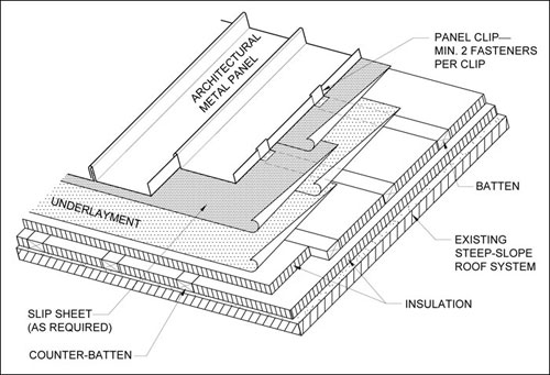
Figure 1: Architectural metal panel roof system with battens and counter-battens
Four roof re-covering system configuration descriptions, similar to those in Chapter 8, are included to assist designers in selecting components for their specifications and assist contractors with project submittals describing roof re-covering system components. The following re-cover system configuration descriptions are provided in Chapter 9:
- Structural metal panel roof system over existing metal panel roof system
- Architectural metal panel roof system over existing low-slope membrane roof system
- Structural metal panel roof system over existing low-slope membrane roof system
- Architectural metal panel roof system over existing steep-slope roof system
Updated construction details
Several details in the volume have been updated. The architectural metal panel construction details underwent the most changes. For instance, there are four new options for architectural eave flashings with water and ice-dam protection membranes and two new options for architectural eave with gutter flashings with water and ice-dam protection membranes.
Furthermore, NRCA now considers eave condition treatment with water and ice-dam protection membranes formulated for high-temperature exposures the preferred practice for addressing eave details to prevent bitumen drippage or membrane slippage.
There also is a new architectural rake edge flashing option with rake edge flashing locked to engage an end-panel pan and continuous cleat fastened to the substrate. NRCA's Manual Update Committee believed the original detail did not adequately secure panel ends to the substrate and this new detail provides better securement.
A new architectural venting ridge cap flashing option was introduced to replace a double Z-closure with perforations on the horizontal leg. The new detail follows the configuration shown in the structural trapezoidal seam and structural vertical seam construction details.
Changes that occurred in all three sets of construction details include NRCA's preference for one-piece (shop-fabricated) metal curb assemblies, welded or soldered, depending on metal. Additionally, a hot or cold stack vent detail, not previously addressed in the metal panel roof systems volume, has been added in each construction details set.
Also, in keeping with NRCA's longstanding intent of providing generic construction details, counterflashing attachment to the substrate is not shown on individual construction details included with the new manual. Instead, the 2012 manual references The NRCA Roofing Manual: Architectural Metal Flashing, Condensation Control and Reroofing for counterflashing attachment options appropriate for different substrate types.
SPF roof systems
The SPF roof system section also contains several noteworthy changes.
For example, because SPF can be directly applied to substrates other than a roof deck, a new chapter, Chapter 2—Other Substrates, was added. Appropriate substrates include base sheets and rigid board insulation. This chapter contains information about common varieties of base sheets and base sheet fasteners used with SPF roof systems.
SPF material and its application are addressed in Chapter 3—Spray Polyurethane Foam. Some changes include a reference to a new ASTM International standard, ASTM D7425, "Standard Specification for Spray Polyurethane Foam Used for Roofing Applications."
The standard addresses SPF that is intended for roofing applications. Within ASTM D7425, there are two classification types, Types I and II. Both types require a minimum compressive strength of 40 pounds per square inch and a density of 2.5 pounds per cubic foot. The significant difference between the two types is the minimum R-value requirement of 5.6 per inch thickness for Type I and 4.1 to 5.6 per inch thickness for Type II.
Chapter 4—Protective Surfacings discusses protective surfacing used with SPF roof systems. Previous editions included information about two types of protective surfacing, coatings and roof membranes. The committee decided the foam in SPF roof systems that incorporated membrane surfacing technically was low-rise foam, so discussion regarding membranes as a protective surfacing was eliminated from the 2012 volume.
Physical and chemical properties play an important role when evaluating coatings. The 2012 volume added descriptions of these properties and their applicable ASTM standards, if available. Physical properties discussed include viscosity/thixotrophy; volume solids; elongation/tensile strength/elasticity; moisture absorption; permeability/permeance/perm rating; fire resistance; oxidation/fungi/algae growth; solar reflectance/reflectivity; and thermal emittance/emissivity.
SPF roof systems with protective coatings eventually will need maintenance and repairs and, ultimately, a "recoat." To assist roofing professionals, a reference to ASTM D6705, "Standard Guide for Repair and Recoat of Spray Polyurethane Foam Roofing Systems," was added. ASTM D6705 outlines general procedures for the repair and recoating of existing SPF roof systems.
New chapters
Three new chapters appear in the SPF manual: Chapter 5—Roof Accessories, Chapter 6—Roof System Configurations and Chapter 7—Roof Re-covering.
Chapter 5—Roof Accessories covers premanufactured roof accessories that may be provided or installed by other trades. There is discussion about equipment curbs, expansion joint covers and skylights, and roof and smoke hatches.
Chapter 6—Roof System Configurations provides descriptions of how roof deck substrates, air and vapor retarders, rigid board insulation and SPF components are combined to design and construct SPF roof systems.
Chapter 6 is intended to be a guide to designers when specifying SPF roof systems and developing project drawing specifications. The configurations provided do not address all possible combinations; however, the configuration descriptions and other portions of the manual can be used as a guide for developing other roof system configurations. Roof system configurations are provided for SPF roof systems over concrete decks, insulated decks and nailable decks.
For example, the system configuration description for an SPF roof system over a nailable deck includes information about roof slope limitations, nailable deck types, air and vapor retarders, SPF, protective surfacing, flashings and roof accessories. The individual components' descriptions provide specific references to locations within other volumes in the current manual series where more detailed information can be found. Also, descriptive roof system illustrations are provided.
The system configurations will help designers select components for their specifications when contractors provide project submittals describing membrane roof system components.
Chapter 7—Roof Re-covering contains general guidelines for re-covering existing roof systems with SPF roof systems. This chapter offers a list of general re-covering recommendations, as well as specific information for SPF applications over existing built-up, polymer-modified bitumen, single-ply and SPF roof systems.
SPF may be applied directly to most adhered roof systems. However, if the existing roof system is not adhered, an overlayment board should be used. Consequently, there are two roof re-covering system configuration descriptions: SPF roof systems over an existing adhered membrane or SPF roof systems over an existing nonadhered single-ply membrane roof system.
Construction details
Construction details are presented in Chapter 8—Construction Details.
Additional information regarding perimeter edge-metal flashings and surface protection is included. SPF roof systems often are terminated with perimeter edge-metal flashing, commonly referred to as foam stops.
For new construction, NRCA recommends the vertical height of a foam stop be a minimum of 1 inch, but in cases where it is less than 1 inch, such as in reroofing situations, NRCA recommends installing a V-groove filled with elastomeric sealant. Committee members believed a foam stop with at least a 1-inch height was high enough to ensure adhesion of the SPF and protection from damage as a result of foot traffic.
Because of the nature of how SPF is installed, applicators need to take extra care during spraying operations. Installers are cautioned to provide overspray protection for surfaces not intended to receive SPF and protective coating. Also, HVAC, ventilation equipment and building air intakes should be masked, sealed or covered.
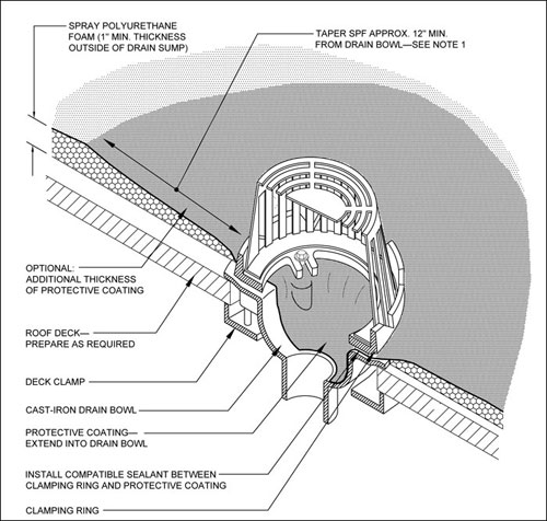
Figure 2: Roof drain in an SPF roof system
Several new construction details were introduced in the SPF manual, including details for a cable penetration, lightning protection terminal and a sheet-metal stack vent (hot or cold).
Updated construction details contain several noteworthy changes, as well. Two changes are related to drainage issues. For roof areas subject to higher volumes of water flow, an option to provide an additional thickness of protective coating was added at perimeter, drain, scupper and gutter details. See Figure 2.
Another modification addresses roof drains. The volume's previous edition illustrated drain strainers placed directly on top of the protective coating and set in sealant; in other words, a clamping ring was not included. The Manual Update Committee prefers clamping rings be provided.
In addition, the detail depicting an SPF enclosure for piping was eliminated. This detail, which entailed a wood enclosure encapsulated in SPF, did not allow for access or maintenance, so the committee removed it.
Some may argue the SPF construction details are not as conservative as the membrane roof system details. The details have been brought to a level of conservatism that matches details that are performing and have performed well in the field for a number of years. As an example, Figure 3 illustrates a roof-to-wall condition, and it does not include a sheet-metal counterflashing.
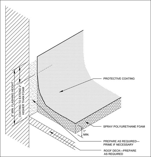
Figure 3: Base flashing for an SPF roof system
NRCA recognizes certain SPF details can perform successfully during the expected service life of a roof system without sheet-metal counterflashings; nevertheless, the primary detail includes a sheet-metal counterflashing.
Final thoughts
The 2010-11 Manual Update Committee responsible for the new manual was composed of practicing roofing contractors who have used the 2008 volume in their operations. With the current update, the committee addresses what they perceived to be the previous edition's limitations. The resulting volume is more comprehensive and better organized—and thus better deserving of being described as a practical reference work from an authoritative source.
You are encouraged to use the 2012 volume for NRCA's most up-to-date guidelines applicable to metal panel and SPF roof systems.
Joan P. Crowe, AIA, and Maciek Rupar are NRCA directors of technical services.
Did You Know?
The NRCA Roofing Manual is the only roofing publication that:
- Is written from an installer's point of view—no other publication offers this emphasis
- Considers the entire roof assembly—other manuals tend to only focus on the roof covering
- Includes reroofing information—other manuals do not address reroofing
- Provides nonproprietary construction details
- Reflects the consensus opinion of roofing contractors
- Is available as a hard copy, contains 392 pages and required more than 100,000 press sheets, 12,000 pounds of paper, 90 pounds of ink and 100 metal plates to produce
- Also is available in electronic format: The NRCA Roofing Manual CD—2012 includes volumes 2009, 2010 and 2011 and allows users to search, view and print manual contents
- Will be mailed (the CD version) to new NRCA members and current members who have paid their 2012 membership dues
- Is available at shop.nrca.net