
Attic ventilation is one of the most widely publicized yet misunderstood concepts in the roofing industry. As a result, many attics fail to have proper ventilation or may not be vented at all. This is unfortunate because attic ventilation, when required, is an important component of a quality roof system. To help roofing professionals understand ventilation issues, I will discuss NRCA recommendations, some industry design guidelines and a sampling of available ventilation products. (For the purposes of this article, it is a given that an attic space should be vented.) I also will provide information about manufacturers and their related products and recommendations as a service to readers. Inclusion of a manufacturer's product or recommendation in this article does not imply endorsement from NRCA nor does NRCA possess or maintain any information about these products' performance records.
Attic ventilation is needed for two primary reasons:
- To lower attic temperatures: lowering attic temperature reduces air-conditioning energy costs and roof deck temperature, optimizes a roof covering's service life (such as asphalt shingles) and minimizes ice damming.
- To promote the removal of excess moisture from attic spaces: removing excess moisture reduces corrosion potential, potential damage to building components, and mold and mildew growth.
Moisture from within buildings generally originates from one of two sources: construction processes or building occupancy activities.
Significant amounts of water vapor can be generated by the curing of wall and/or ceiling plaster or concrete, the combustion process of propane- or kerosene-fired heaters, and drying paint releasing substantial amounts of moisture. Even though water vapor generated by construction processes is temporary, major concentrations in confined areas may cause permanent damage to building components.
Ordinary household functions, such as bathing, cooking and cleaning, can be sources of interior moisture, as well. Improperly vented gas furnaces, moisture from ground water below basements and crawl spaces, and humidifiers also are sources of interior moisture.
NRCA recommendations
The climate in which a building is located significantly will affect the type, direction and degree of moisture migration that will occur into and out of a building.
In climates where temperatures outside a building are colder than inside, the outside air typically will have a relatively low water-vapor pressure. The warmer interior air will exert a higher vapor pressure than the outside air; therefore, the vapor drive will be from the interior of the building to the exterior. In climates where the outside air is predominantly warmer and more humid than the interior air, the vapor drive will be predominantly from the exterior to interior.
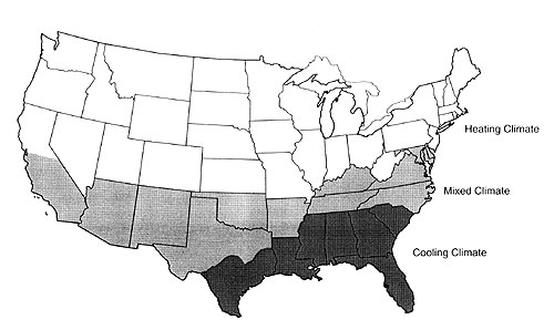
Figure courtesy of The NRCA Roofing and Waterproofing Manual, Fifth Edition.
Figure 1: Shown are U.S. climatic zones used for moisture recommendations
The U.S. can be divided into the following three climatic zones based on the type of environmental control required for most of the year (see Figure 1):
- Heating climate zone: In a heating climate zone, such as Minneapolis, a building's interior generally is heated for a longer portion of the year than it is cooled. A heating climate zone generally is considered to be one that has 3,000 or more heating-degree days, which are units used for estimating fuel consumption.
- Mixed climate zone: A mixed climate zone, such as Baltimore, is one that has up to 4,000 heating-degree days. In a mixed climate, provisions must be made for vapor-drive conditions in heating and cooling seasons.
- Cooling climate zone: In warm, humid climates, such as Orlando, Fla., where buildings often are cooled below ambient outside temperatures, the interior air generally is drier than the exterior air.
For heating and mixed climate zones, NRCA recommends a static, balanced ventilation system with a minimum amount of 1 square foot (0.09 m²) of net-free ventilation area for every 150 square feet (14 m²) of attic space measured at the attic floor level. A balanced ventilation system provides about half the total ventilation area at or near the ridge, such as a ridge vent, and the remaining area at the low points, such as soffit or eave vents (see Figure 2). Balancing ventilation in this manner allows for air intake to occur at the low points and exhaust to take place at the high points. Air movement from low points to high points is aided by natural convection.
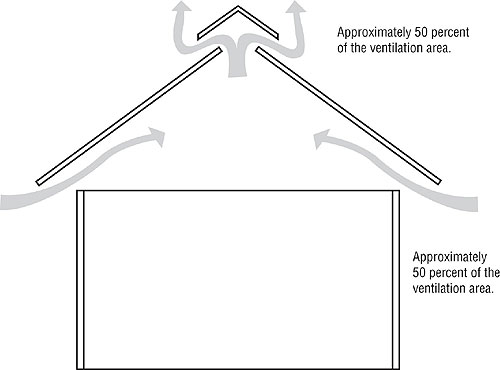
Figure courtesy of The NRCA Roofing and Waterproofing Manual, Fifth Edition.
Figure 2: A balanced ventilation system for attic space shows soffit and ridge vents.
In extremely cold climates or where a building's interior relative humidity is anticipated to be unusually high during peak heating conditions, it may be desirable to increase the amount of ventilation or use a vapor retarder in the ceiling assembly. A residential building's interior relative humidity is considered relatively high when it exceeds 45 percent. NRCA suggests using a vapor retarder on the warm side of attic space insulation when the mean January temperature is 30 F (-1 C) or less.
In cooling climate zones, because the vapor drive predominantly is from the exterior to interior, the purpose of ventilation is to reduce heat buildup. NRCA recommends a static, balanced ventilation system with a minimum amount of 1 square foot (0.09 m²) of net-free ventilation area for every 300 square feet (28 m²) of attic space measured at the attic floor level. This guideline may conflict with an applicable building code's minimum requirements.
For large-volume attic spaces (such as attics with roof slopes greater than 8-in-12 [34 degrees]), you should consider increasing the amount of ventilation. This suggestion applies to buildings in all climate zones.
Instead of a balanced ventilation system, forced or mechanical ventilation may be appropriate. For attics requiring a 1:150 ventilation ratio, ventilation in the amount of 1 cubic foot per minute (CFM) per square foot (0.03 m³/min/m²) or CFM of attic space measured at the attic floor level is effectively equivalent to 1:150 ventilation ratio. For attics requiring a 1:300 ventilation ratio, ventilation in the amount of 0.5 CFM per square foot (0.02 m³/min/m²) of attic space measured at the attic floor level is effectively equivalent to 1:300 ventilation ratio.
Keep in mind, the 1:150 and 1:300 ratio recommendations are minimum ventilation requirements intended to reduce problems associated with moisture accumulation in attics. These ratios are not necessarily directed at minimizing heat gain within attics. If significant attic temperature reduction is desired, substantially greater net-free ventilation typically is required.
Code requirements
Each of the four model building codes—The BOCA National Building Code, Standard Building Code, Uniform Building Code and International Building Code (IBC)—requires attics be ventilated. Generally, building codes require a minimum ventilation ratio of 1:150. Building codes also generally allow for the net-free ventilation area to be reduced to 1:300 ventilation ratio if a vapor retarder is used within a ceiling assembly. Roof system designers are encouraged to consult governing building codes for specific requirements.
IBC, with reference to the International Mechanical Code, also includes provisions if natural ventilation cannot be provided. It stipulates a mechanical exhaust and supply air system should be used in uninhabited spaces, such as crawl spaces and attics. The system should have an exhaust rate of no less than 0.02 CFM and be automatically controlled to operate when the relative humidity exceeds 60 percent.
Other sources
There are additional organizations that offer guidelines for attic ventilation. The U.S. Department of Energy (DOE) offers ventilation guidelines in one of its "Technology Fact Sheets." In general, DOE advises local building requirements be followed, which means adhering to the familiar 1:150 and 1:300 ratios. However, DOE does not recommend electrically powered ventilators because they use more energy than they save; can remove conditioned air; draw in pollutants from crawl spaces; and cause exhaust gases from fireplaces or appliances to enter the building.
The Home Ventilating Institute (HVI) is a nonprofit association of home ventilating product manufacturers. HVI offers a voluntary ratings program where manufacturers can report product performance data. HVI has a slightly different guideline for dividing vent areas. It recommends the ventilation ratio be 60:40 where 60 percent of the net-free ventilation area is located at the eaves and 40 percent is provided by exhaust vents at the ridge or high in the gable area.
HVI also recommends powered attic ventilators be sized by multiplying total square footage of the attic floor by 0.7 to determine the minimum CFM. If a roof is dark or particularly steep, HVI suggests adding 15 percent and a slightly higher rating, respectively. In addition, HVI recommends only soffit vents and not gable vents be used with powered attic ventilators because rain and snow can be drawn into an attic through gable vents.
Ventilation products
Ventilation products essentially fall into two categories—intake and exhaust—and come in a wide range of styles. In addition, ventilation products can be fixed (static) or powered. This article will focus on static ventilation products because NRCA recommends static, balanced ventilation systems. (The product information listed in this article was taken from manufacturers' Web sites at press time. Contact manufacturers directly to verify products meet project specifications.)
As previously mentioned, intake vents should be placed in or near an eave or soffit. When selecting a product, a building's configuration, location of the vent installation and amount of net-free ventilation area provided by the vent should be considered.
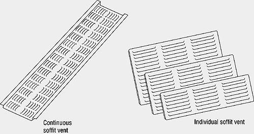
Figure adapted from The NRCA Roofing and Waterproofing Manual, Fifth Edition.
Figure 3: Examples of common intake vents
The most common intake vents are undereave vents and continuous soffit vents (see Figure 3). Intake vents are installed in a soffit and commonly available in vinyl, aluminum or steel and in various colors. The most common undereave shape is rectangular with sizes ranging from 4 inches by 16 inches (102 mm by 406 mm) to 8 inches by 16 inches (203 mm by 406 mm). See Figure 4 for a sample of rectangular undereave vent sizes and their respective net-free ventilation area values.
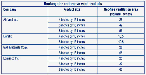
Figure 4: The figure shows a sample of rectangular undereave vent sizes and their net-free ventilation area values.
Circular shapes also are available; however, these units usually are too small to provide sufficient required net-free ventilation area. For example, an 8-inch (203-mm) diameter roof vent will have a net-free ventilation area of about 13 square inches (8388 mm²).
Continuous soffit vents generally are available in aluminum or vinyl and typically are hat-channel-shaped. Figure 5 contains examples of this type of continuous soffit vent.
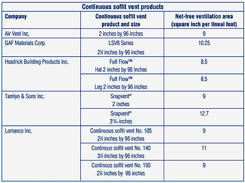
Figure 5: Examples of hat-channel-shaped continuous soffit vents
Another continuous soffit vent option is a vented soffit panel. Several siding manufacturers offer these panels, the advantage being the panels can match the exterior wall siding. Soffit panels may have venting throughout the full panel or just in the center section; however, many vented soffit panels, especially panels with only the center section vented, have much lower net-free ventilation area compared with the continuous soffit vent panel products listed in Figure 6.
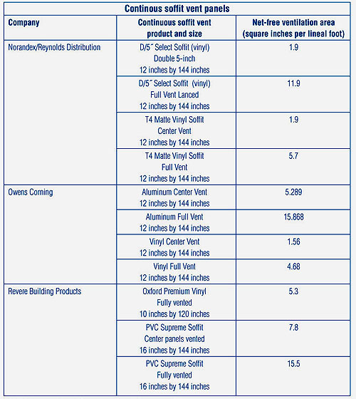
Figure 6: Examples of continuous soffit vent panels
If a building design does not have an eave or soffit, there are unique intake ventilation products to address the situation. COR-A-VENT Inc., Mishawaka, Ind., manufactures the S-400 Strip Vent, a vent made of heat-resistant polypropylene that can be installed directly behind a fascia board. The S-400 Strip Vent has a net-free ventilation area of 10 square inches (6452 mm²). COR-A-VENT also has RS-400 "Raft-A-Vent" for eaves where the rafters are exposed. It is a 22 1/2-inch (572-mm) strip with a net-free ventilation area of 18 3/4 inches (476 mm) and is designed to fit between rafters and on top of blocking.
In reroofing situations where you cannot or do not want to make major modifications to an existing roof deck or wood framing, there are several products to consider. Two products combine intake ventilation with drip-edge flashing. Dallas-based Air Vent Inc.'s Pro Flow™ Vented Drip Edge is an aluminum drip edge that comes in 10-foot (3-m) sections and provides 9 square inches (5807 mm²) of net-free ventilation area per linear foot. Another product is the SV-10 Starter Vent by Lomanco Inc., Jacksonville, Ark., which also comes in 10-foot (3-m) lengths and provides 6.3 square inches (4065 mm²) of net-free ventilation area per linear foot.
An additional product is SmartVent by DCI Products Inc., Clifton Heights, Pa. It is a tapered, plastic vent installed at the soffit edge and under shingles. A continuous slot or series of holes are installed in the roof deck under the plastic vent to allow for air flow. SmartVent has a net-free ventilation area of 9 square inches (5807 mm²) per linear foot. This product could be used in reroofing situations where eave construction cannot be reconfigured or cases where the soffit is blocked with attic insulation.
No matter which soffit vent product you choose, it will not perform properly if the airflow path is obstructed. Make sure there isn't any debris or attic insulation blocking the soffit vents. One method to establish a clear path of air flow is to use insulation baffles. The following manufacturers offer insulation baffles:
- ADO Products, Rogers, Minn.—Durovent and Provent
- Diversifoam Products, Minneapolis—Certivent
- Owens Corning, Toledo, Ohio—Raft-R-Mate
- Perma "R" Products Inc., Grenada, Miss.—Permavent
As with intake vents, there are several exhaust vent design options. The most common exhaust vent types are ridge vents, static exhaust vents and gable vents (see Figure 7).
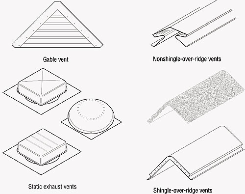
Figure adapted from The NRCA Roofing and Waterproofing Manual, Fifth Edition.
Figure 7: Examples of common exhaust vents
Of the exhaust vent types, ridge vents present some unique advantages. Ridge vents provide maximum efficiency, and studies have shown ridge vents with external baffles pull air from the attic regardless of wind direction or speed. Also, a majority of ridge vent products meet the required amounts of net-free ventilation area.
Ridge vents provide uniform movement of air flow throughout an attic because they are installed along the entire length of a roof. Most products are low-profile and can be covered with shingles, so their appearance on a roof is subtle.
To illustrate that a ridge vent is an efficient, aesthetically pleasing choice, consider a 30- by 50-foot (9- by 15-m) house with a simple gable roof. Such a house would require a net-free ventilation area of 720 square inches (464544 mm²) for the exhaust vents. You would need a ridge vent product that has a net-free ventilation area of 14.4 square inches (9290 mm²) per foot. Most ridge vent products can meet this value. If you were to use static exhaust vents, you would need about 15 individual vents because static exhaust vents typically have a net-free ventilation area of 50 square inches (32260 mm²).
Ridge vents are available in metal, rigid plastic and rolled synthetic mesh goods. Figure 8 displays a partial list of ridge vent products.
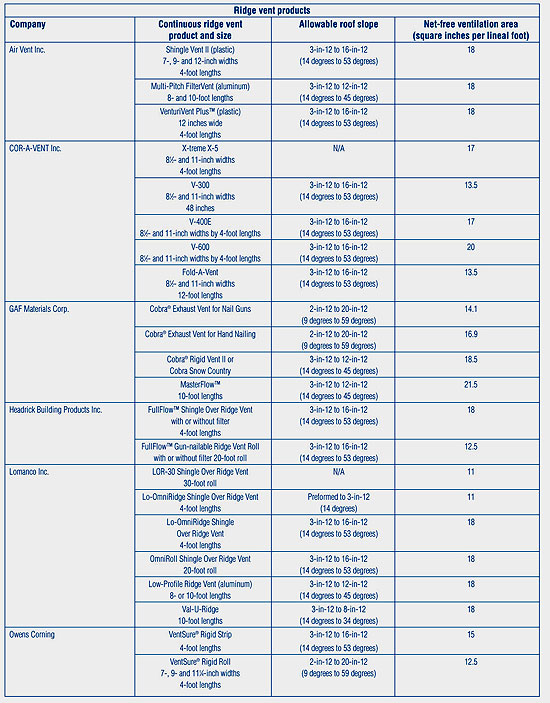
Figure 8: A partial list of ridge vent products
Static exhaust vents are relatively small vents installed near a roof's ridge. They provide a net-free ventilation area of 50 square inches (32260 mm²) to 60 square inches (38712 mm²) per vent and, as previously discussed, a considerable amount of static exhaust vents are needed to meet minimum net-free ventilation area values. Sometimes, static exhaust vents are installed on a roof that also has a ridge vent. This configuration should be avoided—the combination may render the ridge vent ineffective because the static vents create a "short circuit" of the intended air flow (see Figure 9).
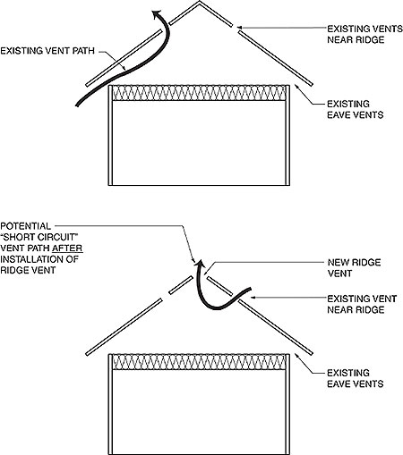
Figure courtesy of The NRCA Roofing and Waterproofing Manual, Fifth Edition.
Figure 9: Common example of a "short circuit" caused by static exhaust vents
Gable-end vents are installed in the vertical walls at the gable end's peak. When gable-end vents are used without intake vents at the eaves, gable-end vents function as intake and exhaust vents and performance depends on wind direction. These types of vents are of limited effectiveness with light winds and/or winds coming from a direction parallel to the gable ends.
In cases where a roof's peak intersects a wall or doesn't have a true ridge (such as on a freestanding shed roof), Figure 10 shows specialty exhaust ventilation products to consider.
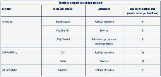
Figure 10: Specialty exhaust ventilation products are an option to consider where a roof's peak intersects a wall or doesn't have a true ridge.
Unique situations
Two design configurations pose unique ventilation problems—cathedral ceilings and hip roofs. Cathedral ceilings are characterized by a compact space between the ceiling and roof deck. NRCA does not recommend installing bitumen-based steep-slope roof coverings (such as asphalt shingles) directly over insulation or insulated roof decks for two reasons. First, subjecting bitumen-based components to excessive heat accelerates the rate at which these products age and deteriorate. Second, there are problems with ice dams and icicles associated with unvented, improperly insulated cathedral ceilings in heating climate zones. For these reasons, NRCA recommends cathedral ceilings be properly ventilated, which means the addition of a ventilation space between the roof deck and insulation.
Roofing professionals sometimes specify 2 x 4 wood members as furring strips to create an air space. Vented nail-base insulation systems also are used, and these products typically provide a 1- to 2-inch (25- to 51-mm) air space. In many cases, the air space depth of these preformed insulation products is not adequate.
The U.S. Army Corps of Engineers' Cold Regions Research Engineering Laboratory (CRREL) researched ventilation and cathedral ceilings. CRREL determined a roof assembly's R-value, slope and airway length (ridge to eave distance) affect the sizing of air space depths and intake areas. As a result of that research, CRREL developed simplified guidelines for sizing ventilation spaces based on those three variables.
CRREL developed graphs for designers to determine appropriate sizing by referencing the airway height or inlet (intake) area. Keep in mind, the research's main purpose was to reduce ice-dam formation on cathedral ceilings. These guidelines may indicate a need for ventilation spaces that are too large to be practically achieved in new or reroofing projects. These graphs can be found in the Moisture Control section of The NRCA Roofing and Waterproofing Manual, Fifth Edition.
Hip roofs also pose unique ventilation problems. One of the most common problems is the ridge on a hip roof is either short or nonexistent. And many hip roofs form large volumetric attic spaces to ventilate. Unfortunately, there is not a lot of information available about venting hip roofs; however, Air Vent does provide some guidance on this subject and offers the following recommendations:
- If there is a ridge, perform the ventilation calculations to verify you can meet the minimum requirements.
- If you cannot meet the minimum requirements by using a ridge vent or there isn't a ridge, Air Vent suggests the use of a powered attic vent with a humidistat/thermostat located close to the ridge or top of the roof. There should be intake vents on all four sides to ensure a balanced system.
- Do not put a ridge vent on a diagonal hip line. It also may act as an intake vent and will be prone to weather infiltration.
One final note
Attic ventilation is a significant aspect of a roof system and should not be ignored. Roofing contractors should be sure they understand attic ventilation issues, as well as grasp the purpose and quality of attic ventilation products.
Joan P. Crowe is an NRCA manager of technical services.
Attic ventilation resources
Refer to The NRCA Roofing and Waterproofing Manual, Fifth Edition, contact manufacturers and visit the following Web sites for more information about attic ventilation.
Organizations
Home Ventilating Institute
Wauconda, Ill.
www.hvi.org
NRCA
Rosemont, Ill.
www.nrca.net
U.S. Department of Energy, Office of Energy Efficiency and Renewable Energy
Washington, D.C.
www.eere.energy.gov/buildings/info/homes/insulatinghome.html
Companies
ADO Products
Rogers, Minn.
www.adoproducts.com
Air Vent Inc.
Dallas
www.airvent.com
Cor-A-Vent
Mishawaka, Ind.
www.cor-a-vent.com
Diversifoam Products
Minneapolis
www.diversifoam.com
Duraflo
Denver
www.duraflo.com
GAF Materials Corp.
Wayne, N.J.
www.gaf.com
Headrick Building Products
Cumming, Ga.
www.headrick.net
Lomanco Inc.
Jacksonville, Ark.
www.lomanco.com
Norandex/Reynolds Distribution
Macedonia, Ohio
www.norandexreynolds.com
Owens Corning
Toledo, Ohio
www.owenscorning.com/acquainted
Perma "R" Products Inc.
Grenada, Miss.
www.leclairindustries.com
Revere Building Products
Akron, Ohio
www.reverebuildingproducts.com
Tamlyn & Sons
Stafford, Texas
www.tamlyn.com