
There is a long-standing but often understated concern about residential and commercial buildings being constructed without through-wall flashing. The common misconception is sheet-metal flashing cut into a wall 1/4 to 3/4 of an inch will be enough to prevent water from getting past the line of counterflashing and/or roof system. However, in most cases, the latter approach, known as saw-cut flashing, essentially becomes a decorative or aesthetic component rather than a functional one.
Functionality
The difference between the two types of flashing is a viable through-wall flashing is functional; permanent; and takes just a little more time, sequencing and craftsmanship when being installed. It is designed to extend from the outer wall surface through the exterior wall covering and beyond wall sheathing to be properly lapped by the moisture retarder within the wall cavity.
Saw-cut flashing is designed to be a surface solution that has the appearance of through-wall flashing but is essentially ineffective. Saw-cut flashing is cheaper, requires less labor to install and is deceptive in its ability to control water within the masonry wall. Through-wall flashing directs any water that penetrates the exterior surfaces to run out at the base of a wall; saw-cut flashing allows the same water to run behind the flashing and can continue down within the wall.
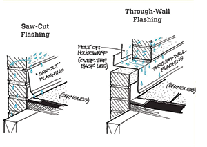 This drawing demonstrates the functions of saw-cut vs. through-wall flashing and the obvious benefits of through-wall flashing. Figure courtesy of Harrison McCampbell, AIA.
In some cases, saw-cut flashing is installed above the line of an existing through-wall flashing. This can create a new problem if the original through-wall flashing diverts water within the wall as it should, only now under the turned-up wall flashing. This is especially critical and detrimental if the old flashing has been removed. Additionally, when caulk is applied along a line of saw-cut flashing, it can further impede trapped moisture trying to escape at this critical point. From a functional standpoint, caulk typically is used as an adhesive to hold new metal in place and close the gap in the mortar where a reglet has been cut. This sealant joint depends heavily on properly tooled mortar joints that serve as added wind-driven rain resistance, which is often not the case. Sealants used must also be applicable to the materials they are in contact with and should have enough elasticity or elongation to allow for the movement of dissimilar materials.
Codes and design
In many new residential construction projects we see, these mortar joints are intentionally applied sloppily or tooled to overrun to give a more rustic or aged appearance. More often than not, this attempt at aesthetics only exacerbates conditions most conducive to wall leaks, as the excess mortar essentially increases the absorptive surface area of a building’s exterior.
According to the 2012 edition of the International Building Code® currently adopted by the state of Tennessee and various counties: “Flashing shall be installed in such a manner so as to prevent moisture entering the wall and roof through joints in copings, through moisture-permeable materials and at intersections with parapet walls and other penetrations through the roof plane.”
Although this is somewhat descriptive, this 2012 reference to flashing is intended to prevent moisture entry, not to redirect it in the event of moisture intrusion. This ultimately boils down to initial design.
The 2012 IBC’s Section 1403.2 states: “… The exterior wall envelope shall include flashing, as described in Section 1405.4. The exterior wall envelope shall be designed and constructed in such a manner as to prevent the accumulation of water within the wall assembly by providing a water-resistive barrier behind the exterior veneer, as described in Section 1404.2, and a means for draining water that enters the assembly to the exterior. Protection against condensation in the exterior wall assembly shall be provided in accordance with Section 1405.3.”
Most conditions would comply with the 2012 IBC, which tends to be the most widely applicable code. Other references are made in the 2009 International Residential Code® currently adopted by Tennessee; however, IRC primarily refers to roof-wall intersections and typically recommends manufacturers’ installation instructions be followed. IRC also focuses on minimum flashing heights and directing water away from walls, not necessarily expelling water from existing walls. Meanwhile, in 2017, the Brick Industry Association published a paper titled “Water Penetration Resistance—Design and Detailing” that states: “Through-wall flashing is an impervious material installed in a masonry wall system to contain water that has penetrated the exterior wythe and direct it back to the exterior.”
The problem is masons typically don’t get the leak call; roofing contractors do. Even if a roofing contractor gets such a call, he or she only would be responsible for installation per the original design.
It is important to note IBC’s 2018 version references flashings in section 1404.4 and states: “Flashings shall be installed in such a manner so as to prevent moisture from entering the wall or to redirect that moisture to the exterior.” The 2018 version goes on to reference virtually all penetrations in the exterior envelope including doors, chimneys, windows, porches, decks, etc. However, it allows for the use of fluid-applied and adhered membranes to be used in accordance with American Architectural Manufacturers Association standards 711 and 714. Sometimes, what we will find is even when these standards are met, shortcuts still occur such as membranes that are poorly lapped, penetrated or short of exposure on the outside of the wall assembly.
Based on the specifications and drawings we often see for residential and commercial buildings in the greater Nashville area, many don’t incorporate the use of through-wall flashing. This is either because it’s too expensive or, more likely, the technique isn’t known to the architect if there is one on the project. We’ve been asked to bid on high-end residential projects where the drawings contain little more than a few fancy elevations and a handful of basic measurements. We promptly and respectfully decline to bid these projects.
Saw-cut flashing on concrete slabs
Photos 1-3 are examples of homes that have received saw-cut rather than through-wall flashing. In Photo 3, there is a concrete second floor patio that ties into a brick wall. In many cases, this concrete tie-in would have been facilitated by wall drainage to a poured slab. Ideally, the slab would be poured with a positive slope away from the house and then be covered with a waterproofing membrane and drainage mat. The slab would have positive slope toward the front of the porch, which ultimately would drain with weeps or drains at the edge of the slab. In addition, it should have been installed at least one course lower.
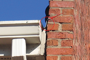 Photo 1: An example of saw-cut rather than through-wall flashing
As a final means of drainage, there should be a through-wall flashing that runs under the lower courses of brick, behind the brick exterior wall and up the substrate interior wall with counterflashing facilitated by the house wrap or moisture retarder. Finally, directly above the through-wall flashing and evenly spaced the entire length of the porch wall, there would need to be weep holes, typically at a maximum of every third brick, for any oversaturation of the brick to be allowed to drain along the line of the through wall.
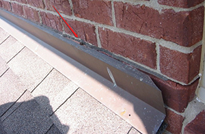 Photo 2: This saw-cut flashing is beginning to pull away from the wall, making it completely ineffective in keeping out water.
However, the photo shows the installing contractor chose to allow the water to bypass the porch and run down the wall. The porch also had negative slope, allowing water to collect at the inside walls and corners, which, in turn, created cascading water at the brick wall between the brick exterior wall and poured concrete porch. Because of the absence of detailed drawings, one might also assume the same detail exists on the lower porch, which ultimately could create below-grade issues over time. With increased surface area, water must be allowed to escape and be directed as far from the base of the structure as possible.
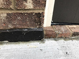 Photo 3: This concrete slab would have benefited from through-wall flashing running under the lower course of brick
Chimney flashing
We constantly see a similar condition with brick or stone chimneys of all ages, especially new construction completed within the past 10 years. In fact, they are frequently our most consistent service call from clients. This is because some contractors give homeowners the runaround for a year on attempted repairs until they reach the end of their average one- to three-year liability period, hoping the leaks will subside long enough for the clock to run out on the warranties. The best approach is to teach designers, train installation crews and provide proper oversight to ensure sequencing and details are followed. It’s imperative all parties involved insist on proper installation details.
To correct chimney flashing issues retroactively, there will need to be significant coordination among contractors in investigative work and/or destructive testing to verify assertions and a follow-up formal repair. Through-wall flashing is the only solution to properly flashing chimneys and is the best and most appropriate option facilitating a long-term correction that should have been addressed at the time of the original construction project. It is critical to coordinate among trades to correct the problem.
Photo 4 shows an example of a job that had a failure in the existing through-wall flashing, which, in this case, was a membrane. To repair this, the length of the existing brick wall to receive the through-wall flashing will need to be removed with enough space to facilitate the proper installation of wall flashing and metal through-wall flashing. The brick can be removed and supported with small masonry jacks to prevent collapse if enough is being removed to compromise the structure. This form of repair is expensive but standard. A critical factor is the interior wall moisture retarder must be properly installed, countering the newly installed metal through-wall flashing so any penetrating water is allowed to run to the edge of the wall. This way, it will not stop short of the edge or outside of the exterior brick wall. This will correct the saw-cut flashing issue and allow proper wall drainage.
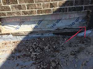 Photo 4: An example of a failure in existing through-wall flashing
In this example, the water test we conducted demonstrated the wall was taking on water at an accelerated rate, the weep holes were not properly functioning and the existing through-wall flashing had failed. However, as testament to the importance of coordination, the customer called Don Kennedy Roofing upset saying he was overseeing the brick removal and the guys on-site told him “there was nothing wrong with the flashing.”
There were, in fact, a number of issues, but the biggest problem was the end dam terminations (corners) were not completely sealed. This is why through-wall traditionally was made from soldered copper. This installation technique ensures the installer’s skill is relied upon rather than an adhesive. Self-adhering membranes used as through-wall flashing primarily are meant for unskilled labor and speed of installation rather than attention to detail. All XYZ joints are at a critical failure point, and roofing contractors have to pay attention to every detail if they hope to prevent future errors.
The importance of training
Reviewing every moisture intrusion point during the design to planning and execution phases is critical, and most people responsible for designing and executing these phases have little to no practical experience identifying them or installing flashing properly. The onus often is on contractors to do designers’ jobs while assuming the liability and risk of legal recourse if things don’t pan out. By extension, the responsibility of knowing what to look for when leaks occur is passed to homeowners. Too many homeowners are faced with the difficult choice of properly repairing these items or ignoring their significance. Too many contractors are unaware of how to identify and eliminate these repeating issues, leading to costly, repetitive and ineffective repairs.
The solution lies in understanding building materials and how they interact with moisture. We have found the best way to address these errors is through extensive and continual training, which focuses on how to properly test for and detect leaks using knowledge of moisture migration and building materials, common sense, and/or methodical analyses and a systemic repair mindset.
Harrison McCampbell, AIA, is a registered forensic architect and owner of McCampbell & Associates, Brentwood, Tenn. Nick Warndorf is director of consulting services for Don Kennedy Roofing Co. Inc., Nashville, Tenn.

