Roof expansion joints are used in roof systems to minimize the effects of stresses and movement of a building's components. Roof expansion joints prevent building stresses from splitting, buckling, ridging or damaging a roof system.
The expansion-joint detail for single-ply membranes has evolved through the years. The first expansion-joint detail appeared as Detail K-1 in the second edition of The NRCA Roofing and Waterproofing Manual published in 1985. This detail depicted an expansion joint specifically for PVC membrane roof systems. The expansion joint was constructed out of two wood nailers that essentially were sized to be the same height as the roof insulation. Compressible insulation was installed between the nailers. At the top surface, the joint was filled with flexible tubing and capped with a PVC flashing strip welded to the membrane on each side. The flexible tubing and flashing strip accommodated the expected movement.
The detail remained the same in the manual's third edition issued in 1989.
In 1995, the manual's fourth edition divided single-ply membrane roof systems into two categories—thermoplastics and thermosets—and the expansion-joint detail was shown in details TP-7 and TS-7.
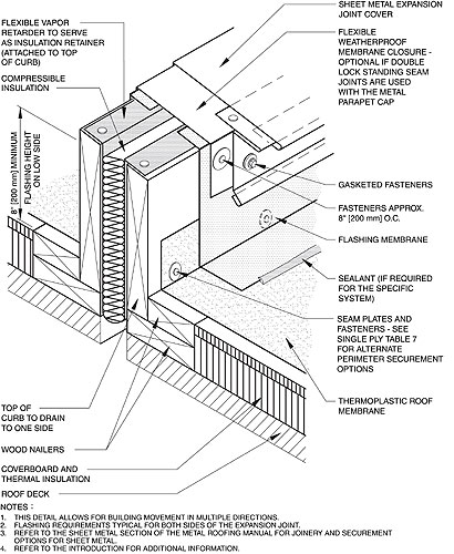
The details were similar except for how the membrane was flashed at the expansion joint. However, compared with the detail's previous version, there was a significant change to the expansion joint's profile. Wood curbs and nailers were added to make a flashing height of 10 inches (254 mm). Instead of a membrane flashing strip, a sheet-metal expansion-joint cover was incorporated to accommodate movement. A flexible membrane also was added as a secondary layer of protection under the sheet-metal cover. A flexible vapor retarder was included to serve as an insulation retainer.
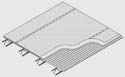
In the manual's fifth edition, the detail was altered again with two notable changes—the sheet-metal expansion-joint cover was redesigned and the flashing height was reduced to 8 inches (203 mm) as shown in the figure. A detail that incorporates a prefabricated expansion-joint cover also was included.
Expansion joints in a roof assembly should be at the same location as the building's structural expansion joints and extend across the entire width of the roof and continue through the roof edge or perimeter. Roof expansion joints should be designed to accommodate contraction and expansion. For additional design considerations, refer to The NRCA Roofing and Waterproofing Manual, Fifth Edition.