Within the past few years, ASCE 7, "Minimum Design Loads for Buildings and Other Structures," published by the American Society of Civil Engineers, increasingly has been used to determine design wind loads, particularly because it is referenced in the 2000 edition of the International Building Code (IBC). Recently, ASCE 7's 2002 edition became available; it is referenced in IBC's 2003 edition. Because many jurisdictions soon may begin requiring compliance with IBC 2003, it is important you are aware of the changes in ASCE 7.
ASCE 7's new edition includes several changes and additions that apply to the calculation of roof assemblies' wind loads. Unfortunately, the changes are not delineated in the document, and it is a laborious process to determine what changes were made. I tracked the changes, and following is an overview of those pertaining to calculating roof assemblies' wind loads. (Note: Additions and changes pertaining to primary structural elements, such as beams, columns, shear walls and diaphragms that provide support and stability for the building, are not addressed in this article.)
Parapets
6.5.12.4 is a new section pertaining to parapet loads. This section directly applies to loads on parapet base flashings, which previously were not addressed in ASCE 7. When determining base flashing loads, the suction pressure on the windward parapet's roof side is determined by using the same coefficient used for the adjacent roof area.
For example, using ASCE 7's Figure 6-11B for a low-rise building with a low-slope roof system, the external pressure coefficient at the roof's perimeter is -1.8 (assuming an effective wind area of 10 square feet [0.93 m²]). Therefore, the suction coefficient for the base flashing in the perimeter zone also is -1.8. In the roof's corner areas, the coefficient is -2.8, and the suction coefficient for the base flashing in the corners also is -2.8.
If the base flashing is applied to a solid parapet, such as a cast-in-place parapet, there is no parapet cavity or internal pressure. However, if the parapet has a cavity (even if filled with batt insulation), the parapet typically has internal pressure. If the parapet's exterior side is sealed but air from within the building can migrate into the parapet cavity (which would be common with stud construction), the building's internal pressure coefficient (from ASCE 7's Figure 6-5) also applies to the parapet cavity. In this scenario, the load on the base flashing is equal to the adjacent roof area.
If the base flashing is applied to a parapet that has a cavity and the parapet's exterior side is air-permeable, such as metal siding, the positive pressure on the wall siding is transferred to the parapet cavity and base flashing. Using the previous example, the positive pressure coefficient is +1 (from ASCE 7's Figure 6-11A). In this case, the loads on the base flashing are higher than the loads on adjacent roof areas. (See "Example of roof and parapet wind loads.")
When base flashing is fully adhered, it has sufficient wind resistance in most cases. However, when base flashing is mechanically fastened, typical fastening patterns may be inadequate depending on design wind-load conditions. Therefore, it is imperative base flashing loads be calculated and attachment be designed to accommodate the loads. It also is important designers recognize and specify different attachment spacings in parapet corner regions versus regions between corners.
Now that parapet load criteria are available, it also is incumbent upon manufacturers to re-evaluate their base flashing criteria and make adjustments where necessary.
Rooftop equipment
ASCE 7's Figure 6-19 was revised to include rooftop equipment. Previous ASCE 7 editions did not address wind loads on rooftop equipment. Before calculating loads on rooftop equipment, a designer should review the commentary pertaining to the figure to be aware of its limitations. Although the commentary is not part of the standard, it consists of explanatory and supplementary material designed to assist in applying the standard's requirements.
The 2002 commentary recommends using a minimum gust effect factor of 1.1. Although not noted in the commentary, high uplift also occurs on the tops of rooftop units. The uplift force may be a significant fraction of the horizontal force, so a designer also should consider uplift load.
Domes
ASCE 7's Figure 6-16 was added to provide external pressure coefficients for domed roofs. Before the 2002 edition was released, coefficients for domes had to be determined via special wind-tunnel testing or from recognized literature. A designer should review the commentary pertaining to this figure to be aware of the figure's limitations.
Exposure
Another change in ASCE 7 relates to exposure. Exposure refers to the characteristics of ground roughness and surface irregularities in a building's vicinity; exposure influences wind loading. The smoother the terrain, the greater the wind load.
Exposure A, which represented large city centers, was eliminated from the 2002 edition. New York City, for example, now is classified as Exposure B.
Also, Exposure D was expanded to include smooth mud flats, salt flats and unbroken ice. Exposure D previously applied only to areas along shorelines.
The requirements for the distance of upwind terrain conditions were changed for all exposures. In addition, the inland extension from the shoreline of Exposure D was changed.
Interpolation between exposure categories now is permitted, and guidance for interpolating was added to the commentary.
Simplified procedure
In the standard's previous edition, a simplified procedure for determining wind loads (Method 1) was added. If a building met specific criteria, loads could be determined from a table rather than by calculations. In the 2002 edition, Method 1 has been expanded.
Previously, the method was limited to buildings up to 30 feet (9.1 m) and roof slopes less than 2-in-12 (10 degrees). Method 1 now can be used for buildings up to 60 feet (18.3 m) and on gable roofs with slopes up to 12-in-12 (45 degrees) and on hip roofs with slopes up to 6-in-12 (27 degrees).
Method 1 also was limited to buildings without overhangs, but a table was added in the 2002 edition for overhang loads. In addition, the previous edition included tables for partially enclosed buildings; however, Method 1 now is permitted only for enclosed buildings.
When using Method 1, it is important designers realize the tabulated values are for a 30-foot- (9.1-m-) high building in Exposure B with an importance factor of 1. For other heights and/or exposures, designers should use the appropriate factor from the Adjustment Factor Table in ASCE 7's Figure 6-3. If a building has an importance factor other than 1 (as derived from Figure 6-1), tabulated loads must be adjusted by an importance factor.
Gable and hip pressure
The allowable roof slope ranges for ASCE 7's Figures 6-11B, 6-11C and 6-11D were changed.
Figure 6-11B for gable roof systems now is limited to slopes less than or equal to 1.5-in-12 (7 degrees). It previously was for slopes up to 2-in-12 (10 degrees).
The standard's Figure 6-11C for gable roofs and hip roofs now is limited to slopes between 1.5-in-12 and 6-in-12 (7 degrees and 27 degrees) rather than the previous 2-in-12 and 7-in-12 (10 degrees and 30 degrees). The pressure coefficients also have been changed for Figure 6-11C.
Figure 6-11D for gable roofs now is limited to slopes between 6-in-12 and 12-in-12 (27 degrees and 45 degrees). It previously was for slopes between 7-in-12 and 12-in-12 (30 degrees and 45 degrees).
Impact-resistant glazing
If a building is located in a wind-borne debris region within a hurricane-prone region (as defined by the standard), special provisions apply to glazing, including glazing in skylights. Several changes were made to these provisions.
For example, two standards, ASTM E1886, "Test Method for Performance of Exterior Windows, Curtain Walls, Doors, and Storm Shutters Impacted by Missiles and Exposed to Cyclic Pressure Differentials," and ASTM E1996, "Standard Specification for Performance of Exterior Windows, Curtain Walls, Doors and Storm Shutters Impacted by Windborne Debris in Hurricanes," pertaining to wind-borne debris loads and testing were referenced.
Also, in the standard's previous editions, glazing above 60 feet (18.3 m) was exempted from wind-borne debris provisions. However, glazing no longer automatically is exempt. If an existing building within 1,500 feet (458 m) of the building being evaluated has an aggregate-surfaced roof system, glazing in the evaluated building must be protected to a height of 30 feet (9.2 m) above the aggregate-surfaced roof system. For example, if a new 500-foot- (152-m-) tall building is being designed and a 400-foot- (122-m-) tall building with an aggregate-surfaced roof system is within 1,500 feet (458 m), the glazing in the new building must be protected up to a height of at least 430 feet (131 m) or the building must be designed as partially enclosed. Such protection must be provided 30 feet (9.2 m) above the height of the aggregate-surfaced roof system because some aggregate can blow off roofs in upward trajectories.
The commentary notes that loose roof aggregate not protected by an extremely high parapet should be considered a debris source. The commentary does not define "extremely high" because of a lack of quantifying data. The parapet height needed to prevent aggregate blow-off will be a function of building height and basic wind speed. A designer's judgment will be needed to assess the suitability of parapet height.
The commentary also notes that if loose aggregate is proposed for a new building, the aggregate should be considered a debris source because it can blow off and propel into glazing on the building's leeward side.
Although other missile types can reach higher than 60 feet (18.3 m) above grade, at such high elevations, loose roof aggregate has been the predominate debris source in previous wind events.
In earlier standard editions, glazing in wind-borne debris regions could be protected or a building could be designed as partially enclosed (designed for higher internal pressure). But with the 2002 edition, the option of designing for higher internal pressure no longer is permitted for some building types.
Glazing in Category IV buildings, which include hospitals, fire and police stations, and other essential facilities, now must be protected. The following Category III facilities also must have protected glazing: health care, jail and detention, power generating and public utility. The reason protected glazing now is required for such buildings in wind-borne debris regions is that if glazing is not protected, the potential for glazing breakage and subsequent water infiltration is high. If breakage were to occur, continued operation of these important facilities could be jeopardized.
End result
The additions and changes in ASCE 7's 2002 edition are based on new research and in response to designers' desire for a more user-friendly standard. The new edition contains important information for roof system designers, and I encourage its use because it is the current state of the practice in the United States.
Determining design wind loads is a key factor in ensuring high-wind performance of roof assemblies. Unless loads appropriately are determined and designed for, blow-off problems can occur. ASCE 7's wind-load provisions are relatively easy to use for those familiar with the standard; however, it is just as easy for a novice to make serious errors. First-time users of the standard should become familiar with it before determining wind loads.
To purchase ASCE 7, call (800) 548-2723 or access www.asce.org.
Thomas L. Smith is president of TLSmith Consulting Inc., Rockton, Ill., and a member of the ASCE 7 Committee and ASCE's Task Committee on Wind Loads.
Example of roof and parapet wind loads
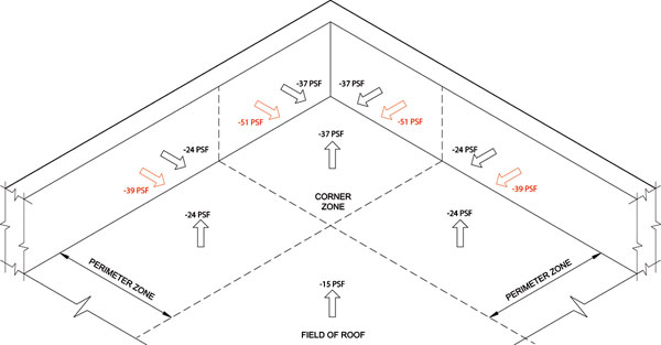
For this example, the following parameters were used:
Basic wind speed: 90 mph (40 m/s)
Exposure: B
Roof height: 30 feet (9.1 m)
Parapet height: Less than 3 feet (0.9 m)
The parapet suction loads in black type are for a condition where the exterior face of the parapet cavity is sealed. The loads in red type are for a condition where the exterior face of the parapet cavity is an air-permeable material, such as metal siding. For the latter condition, the parapet base flashing loads are much larger than the loads on the roof (a 38 percent increase in the corners and 63 percent increase between the corners).