When the American Society of Civil Engineers (ASCE) first published ASCE 7, "Minimum Design Loads for Buildings and Other Structures," in 1988 (it previously had been published by the American National Standards Institute as A58.1), few people in the construction industry were familiar with the standard. However, during the past several years, the standard increasingly has been used to determine design wind loads, in part because the International Building Code (IBC) began requiring the standard's use in its 2000 edition.
ASCE 7's 2005 edition (ASCE 7-05)—the most current edition—is referenced in the International Building Code, 2006 Edition. The next edition of ASCE 7 is scheduled to be released in 2010.
ASCE 7-05 includes some changes and additions from its 2002 edition that affect the calculation of wind loads on roof assemblies and rooftop equipment. Unfortunately, the document does not clearly note what changes have been made, and determining the changes is a laborious process. I have tracked the changes, and following is an overview of those changes pertaining to calculating wind loads on roof assemblies and rooftop equipment.
Additions and changes pertaining to primary structural elements, such as beams, columns, shear walls and diaphragms that provide support and stability for buildings, are not addressed in this article.
Rooftop equipment
Provisions for calculating wind loads on rooftop equipment first were included in ASCE 7's 2002 edition. Based on additional research that was conducted after development of the 2002 provisions, it was discovered the provisions were nonconservative.
The force coefficients used to determine loads on rooftop equipment are shown in ASCE 7-05's Figure 6-21. The coefficients are the same as in the 2002 edition; however, new guidance for load determination is provided in the figure's commentary.
Although the commentary is not part of the standard, it provides explanatory and supplementary material to assist in applying the standard's requirements.
To better understand how to appropriately use the standard and commentary, see "Calculating Wind Loads and Anchorage Requirements for Rooftop Equipment," ASHRAE Journal, volume 48, number 3, March 2006 issue.
Calculating loads and determining anchorage requirements for rooftop equipment can be time-consuming. To minimize the time it takes to determine anchorage requirements, FEMA 577, "Design Guide for Improving Hospital Safety in Earthquakes, Floods, and High Winds: Providing Protection to People and Buildings," provides a table with an attachment schedule for fans, small HVAC units and relief air hoods. The table is based on a 30-foot-tall building in Exposure Category C (flat open country) with a basic wind speed of 90 mph.
For the base case, anchorage recommendations can be determined quickly. For other exposure categories or wind speeds or heights up to 200 feet, attachment can be adjusted with a simple calculation illustrated in the table's notes.
Because the table was developed for hospitals, an importance factor of 1.15 (which increases the loads by 15 percent) is used with a safety factor of three. For noncritical buildings, a safety factor of two commonly would be used. Therefore, for noncritical buildings (such as Category I and II buildings, as defined in ASCE 7-05), the number of fasteners recommended in the table could be reduced by one-third.
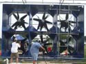
The importance of adequately anchoring rooftop equipment cannot be overemphasized. Rooftop equipment often is blown off during storms that are well below design wind speeds. Blown-off equipment can puncture a roof membrane and lead to progressive lifting and peeling, as well as damage other buildings and vehicles (see Photo 1) and injure people. A substantial amount of water also can enter a building where equipment has blown off curbs (see Photo 2).
Some people mistakenly believe large rooftop units are of sufficient weight to keep the units in place. This may sometimes be the case, but I have seen many large, heavy units that have blown off their curbs. Therefore, regardless of a unit's size or weight, design wind loads and attachment requirements always should be determined.
Gooseneck vents also should receive special consideration. They require a substantial number of fasteners (see Photo 3) because they have little weight to counteract wind load and large surface areas to catch wind.
Canopies
ASCE 7-05 also includes new provisions for open canopies and walkways, which the standard refers to as "free roofs." Figures 6-18A to 6-18D in ASCE 7-05 are for a building's main wind-force-resisting system (beams and columns). Figures 6-19A to 6-19C are for components and cladding; these figures apply to roof assemblies.
The figures have coefficients for "clear wind flow" and "obstructed wind flow." The clear wind flow case applies to walkways and canopies at building entries. The obstructed wind flow case applies to an open building (one with no walls) that is used for storage. A common example of an obstructed wind flow case is an open building at a lumber yard that is used to store lumber or other materials.
The loads acting on a roof assembly are different when the area below the roof is open (such as a canopy) versus when materials are stored below an open roof, such as at a lumber yard.
The canopy provisions are a welcome addition to ASCE 7-05. In previous editions, designers did not receive guidance for determining wind loads on canopies, roof assemblies or structural elements. As a result, in the past, failure of roof coverings and of entire canopies has occurred even in relatively modest storms (see Photo 4).
Glazing protection
ASCE 7 first addressed the issue of glazing breakage caused by wind-borne debris in its 1995 edition. In each edition published since (1998, 2002 and 2005), changes regarding glazing breakage have been made.
Glazing can be protected by shutters, laminated glass or polycarbonate. When glazing breakage provisions were added in 1995, the shutter industry was in its infancy and the concept of protecting glazing was new and controversial. As the shutter industry matured and the concept of protected glazing became better understood, ASCE 7's requirements were strengthened.
ASCE 7-05 requires protected glazing for almost all buildings in wind-borne debris regions. Wind-borne debris regions occur only in hurricane-prone regions. (ASCE 7-05 defines these region types.) Unprotected glazing is allowed on Category 1 buildings (such as agricultural facilities, certain temporary storage buildings and minor storage facilities). Unprotected glazing also is allowed for glass above 60 feet from grade (provided an aggregate-surfaced roof is not within 1,500 feet).
When calculating roof assembly loads on an existing building in a wind-borne debris region, it is important for a designer to determine whether the glazing (including skylights) is protected. If it is not, I believe the glazing should be considered an opening. If the opening is sufficiently large (as defined in ASCE 7-05), the building should be designed as a partially enclosed building, which will result in increased loads on the roof assembly (see Photo 5).
Method 1
Method 1 is a simplified calculation procedure for determining wind loads. Design pressures can be determined from ASCE 7-05's Figure 6-3 for roof heights up to 60 feet. In ASCE 7's 2002 edition, Method 1 was not to be used for buildings subject to topographic effects. However, in ASCE 7-05, Method 1 can be used for such buildings.
When you use Method 1, note the pressures given in Figure 6-3 are for Category II (noncritical) buildings with roof heights of 30 feet in Exposure Category B (urban, suburban and wooded areas). For other building categories, roof heights or exposures, the tabulated pressures need to be adjusted. This is a simple calculation but one that easily could be overlooked.
Parapets
Criteria for determining loads on parapets was added in ASCE 7's 2002 edition. For discussion about those provisions, see "Detailing ASCE 7's changes: Updated ways to determine design wind loads," July 2003 issue, page 26.
Determining loads is particularly important for mechanically attached base flashings (including flashings that have nailed base sheets) because—unlike fully adhered base flashings, which typically are strong enough to resist loads—mechanically attached base flashings' resistance is a function of how many fasteners are needed. The 2002 edition's commentary has been modified slightly in ASCE 7-05 to provide additional guidance for calculating parapet loads.
Exposure categories
Exposure refers to ground roughness and surface irregularities in a building's vicinity. The smoother the terrain, the greater the wind load. The criteria for defining Exposure Categories B and D are modified in ASCE 7-05.
It is easy to determine the appropriate exposure for many building locations, but with certain locations, it takes some effort. It is important to assess the exposure correctly because loads increase dramatically with the change between Exposure Categories B and C and Exposure Categories C and D.
For example, if a building is located in Exposure Category C and designed for Exposure Category B, the loads will be undercalculated by 40 percent (a significant error). Conversely, if a building is located in Exposure Category B and designed for Exposure Category C, the 40 percent load increase could result in an unnecessary extra expense for materials and installation.
Go forth and use
The additions and changes in ASCE 7-05 are based on new research and experience and provide designers with a more user-friendly standard. The updated edition contains important information for roof system designers, and I encourage the standard's use because it is the current state of practice in the U.S.
Determining design wind loads is a key factor in ensuring long-term performance of roof assemblies. Unless loads appropriately are determined and designed for, blow-off problems can occur.
ASCE 7-05's wind-load provisions are relatively easy to use for those familiar with the standard; however, it also is easy for a novice to make serious errors. If you are a first-time user of the standard, become familiar with it before determining wind loads.
To purchase ASCE 7-05, call ASCE at (800) 548-2723 or access pubs.asce.org/books/standards.
Thomas L. Smith, AIA, RRC, is president of TLSmith Consulting Inc., Rockton, Ill., and a member of the ASCE 7 Task Committee on Wind Loads.
On many roofing projects, a mechanical contractor is responsible for installing and anchoring rooftop equipment. In these cases, the roof system designer should request equipment be anchored to resist the loads derived from ASCE 7-05. If equipment is anchored inadequately, equipment blowoff can lead to roof membrane blowoff, which could be misdiagnosed to have initiated the problem rather than the equipment.
During reroofing projects, rooftop equipment often is temporarily removed and reinstalled by roofing contractors.
In these situations, the equipment should be re-anchored per ASCE 7-05. FEMA 577's Table 4-1, which is shown in the figure, can be a valuable aid.
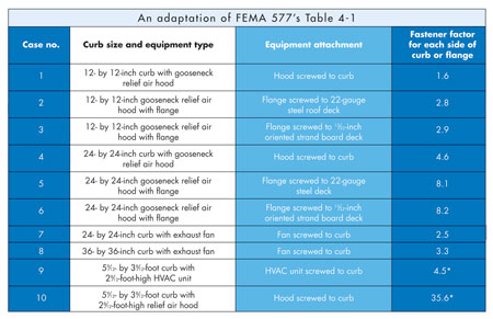
Notes:
- The loads are based on ASCE 7-05. The resistance includes equipment weight.
- The base case for the tabulated numbers of No.12 screws (or 1/4 pan-head screws for flange-attachment) is a 90-mph basic wind speed, 1.15 importance factor, 30-foot building height, Exposure C, using a safety factor of three.
- For other basic wind speeds, multiply the tabulated number of No.12 screws by (V2D/902) to determine the required number of No.12 screws (or 1/4 pan-head screws) required for the desired basic wind speed VD (mph).
- For other roof heights up to 200 feet, multiply the tabulated number of No.12 screws by (1.00 + 0.003 [h-30]) to determine the required number of No.12 screws (or 1/4 pan-head screws) for buildings between 30 and 200 feet in height.* This factor only applies to the long sides. At the short sides, use the fastener spacing used at the long sides.
Roof Wind Designer
NRCA offers Roof Wind Designer, a Web-based program for calculating roof-uplift loads. The program is based on ASCE 7-05's Method 1.
There are several advantages of using Roof Wind Designer, which follow:
- In addition to calculating design-uplift pressures for the field, perimeter and corner areas, Roof Wind Designer also calculates the pressures with a safety factor of two (which is recommended by ASTM D6630, "Standard Guide for Low Slope Insulated Roof Membrane Assembly Performance").
- Roof Wind Designer calculates the perimeter and corner zones' widths.
- Roof Wind Designer provides guidance for selecting a laboratory-tested roof assembly (such as a system with an FM Approval listing of 1-60) based on the factored load (the design load multiplied by the safety factor).
NRCA developed Roof Wind Designer with the support of the Midwest Roofing Contractors Association and the North/East Roofing Contractors Association. It is available for free at www.roofwinddesigner.com.